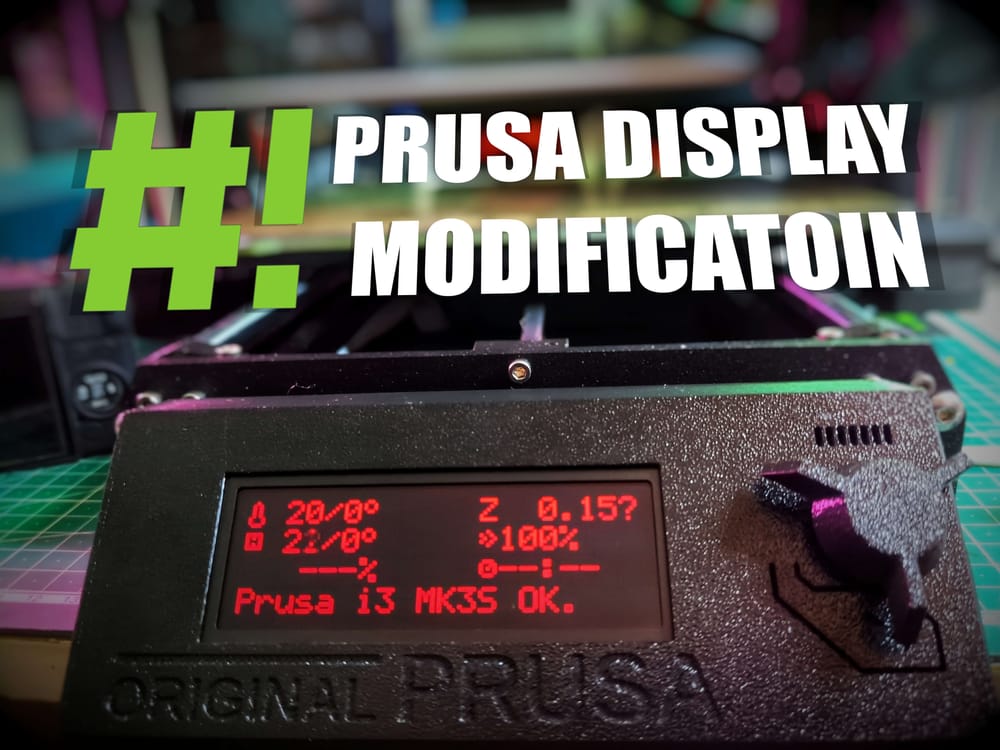
Prusa MK3S+ LCD Modification
Synopsis
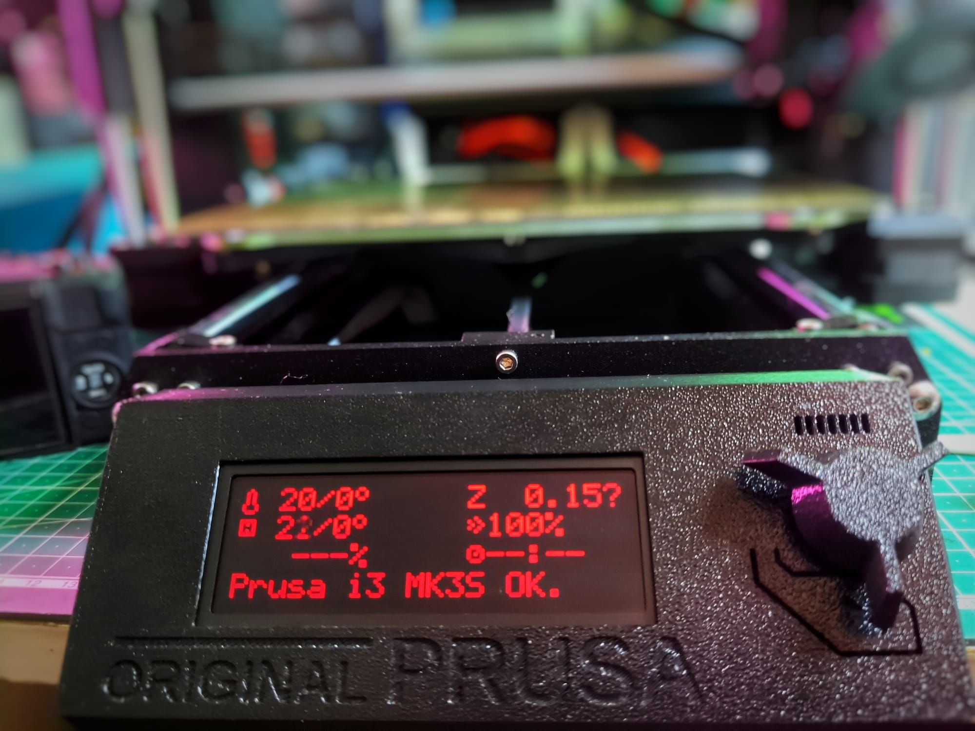
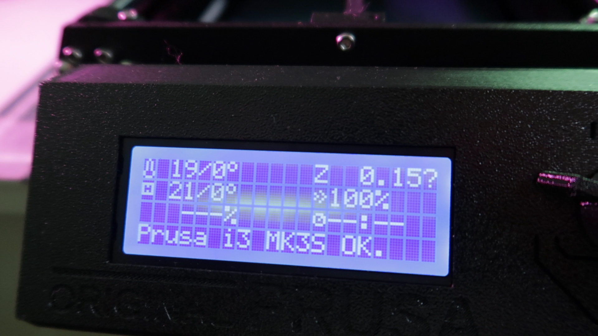
The standard LCD for my Prusa MK3S+ does its job. However, it is nothing to write home about. In my case, I have a small area in the middle of the display that is washed out. I believe this is due to some kind of pressure from the backside.
Let's customize this display and add some extra pieces of flair! In this article, I will explain how I swapped out the standard blue and white 2004A display with a red and black one. I have the black version of the MK3S+ and I think red and black goes better with the black printed parts. It makes it look like it wants to print for the dark side of the force. Let's get started!
Tools
You will need the following tools:
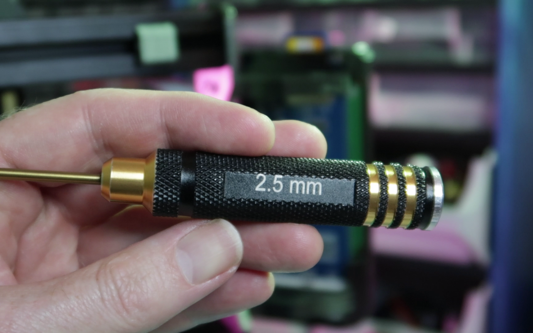
- 2.5mm Hex Driver
- Soldering Iron and Solder
- Solder Wick
- Soldering Flux
- A plastic spudger
Parts
For this project, you will only need a single new component; namely a new 2004A LCD. These displays come in various color combinations: white, green, yellow, purple and red. Choose the color that tickles your fancy the most.
Disassembly
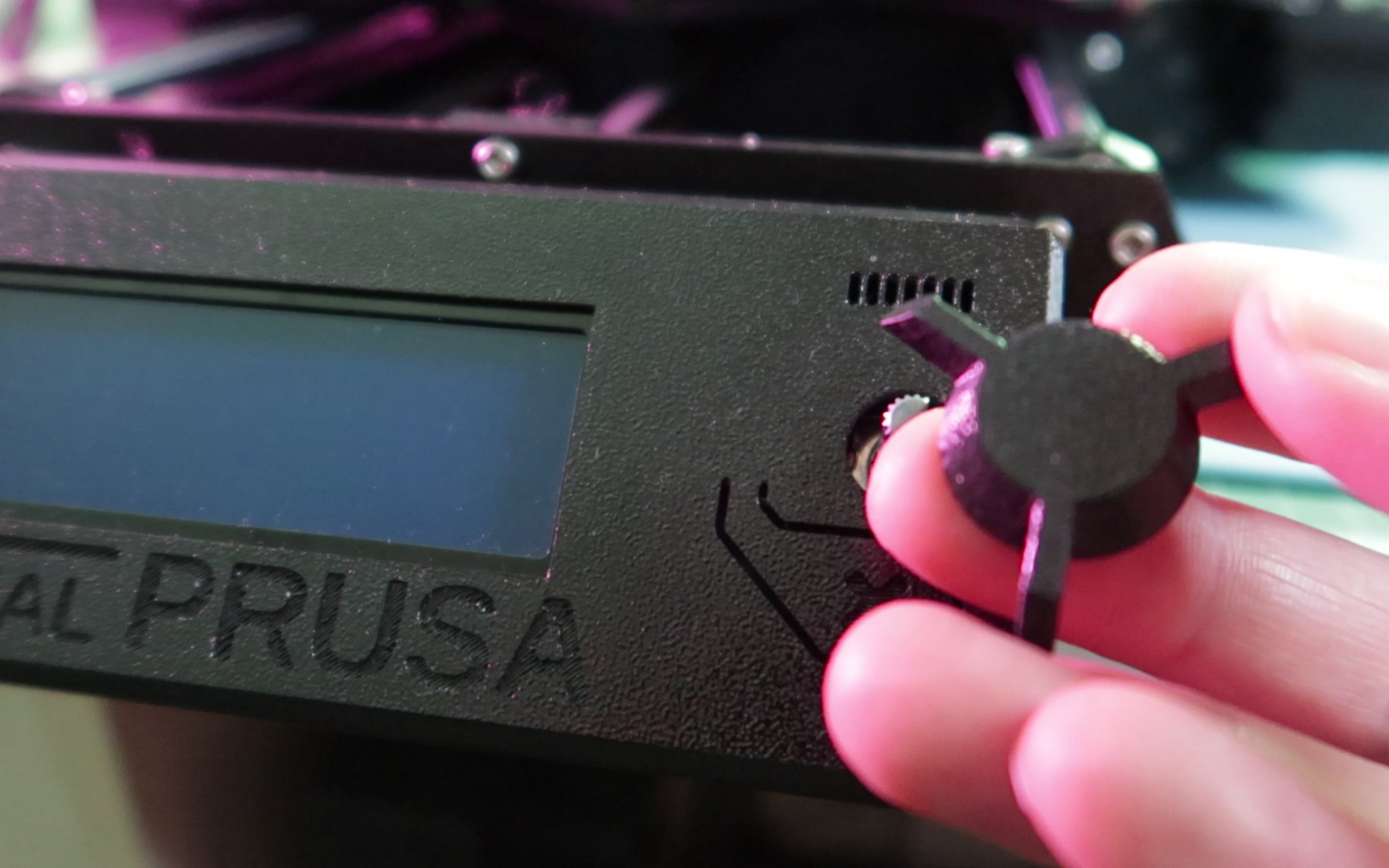
Firstly, unplug your printer and remove the knob from the rotary encoder on the front.
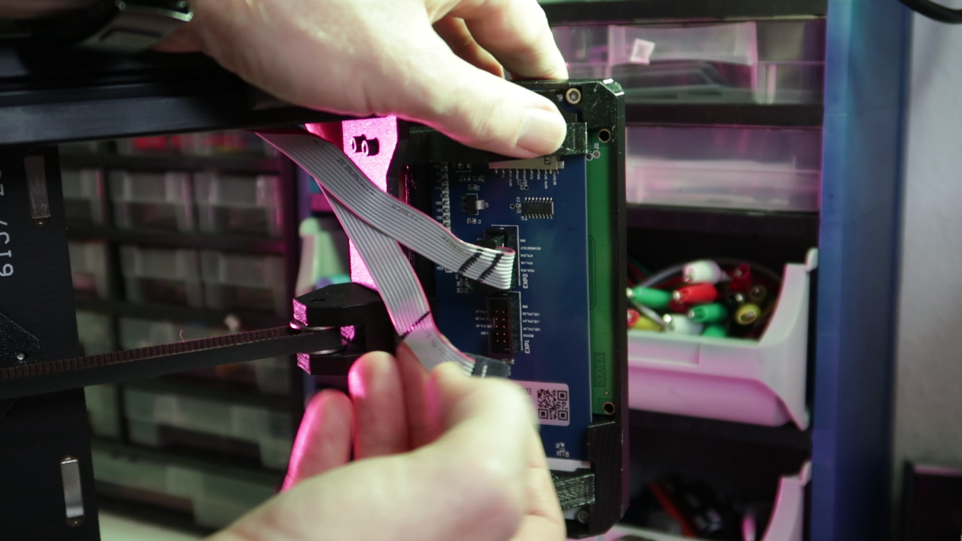
Now, lay it on it's left side. Specifically, the side with the power supply. By laying down on the left side, you can avoid putting pressure and cracking the 3d printed grill for the main board enclosure. Take note of the ribbon cables attached to the bottom of the display module. You can tell them apart by the marker stripes marked on each individual cable. Take note of their positions, then detach them. You will need to know this when reassembling the module to the holder.
Underneath the display, we need to remove two hex screws with a 2.5mm hex driver
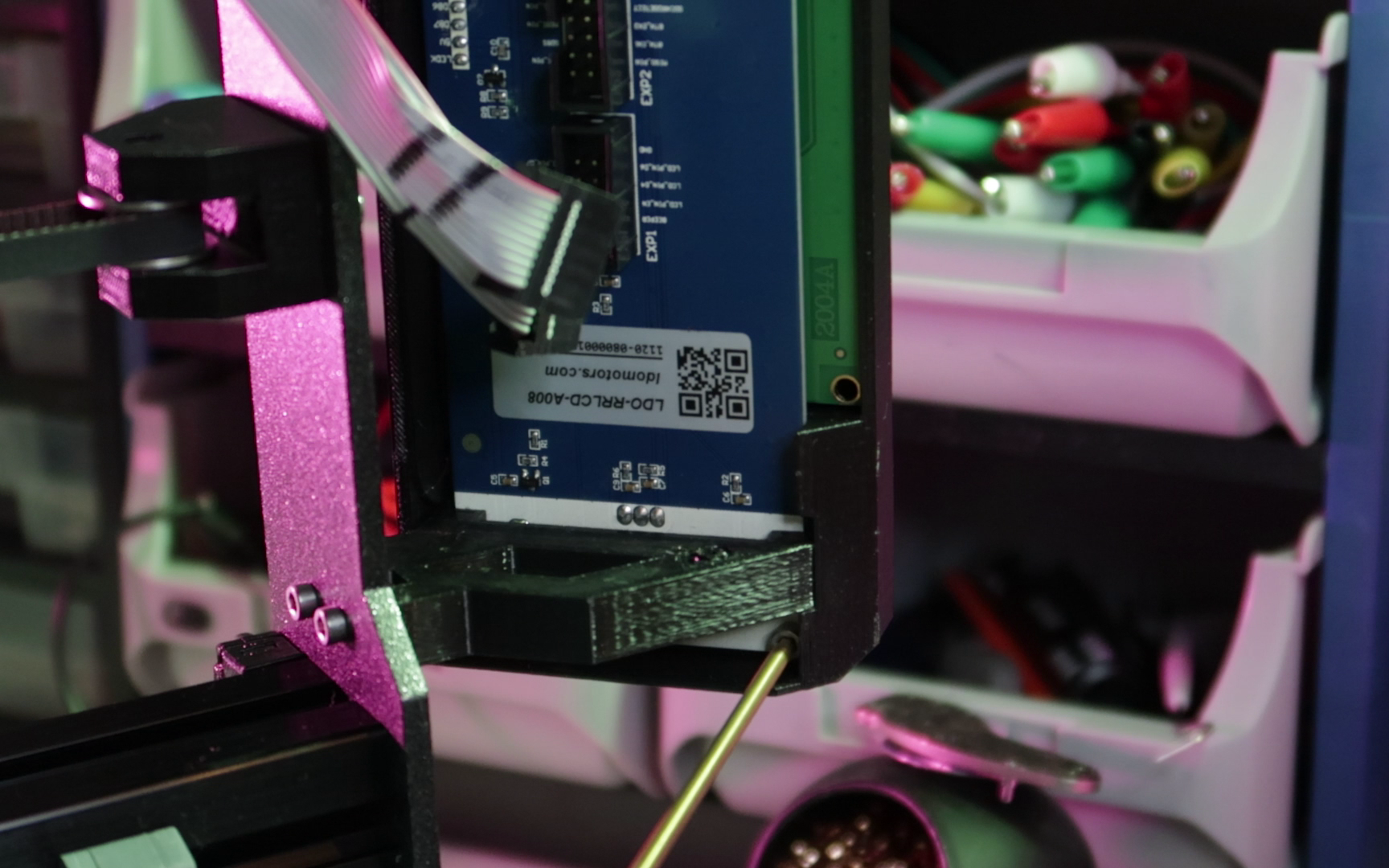
Unscrewing both screws and place them in a safe place. Remove the 3d printed display cover. Push up the snap-fit nub and pull it off
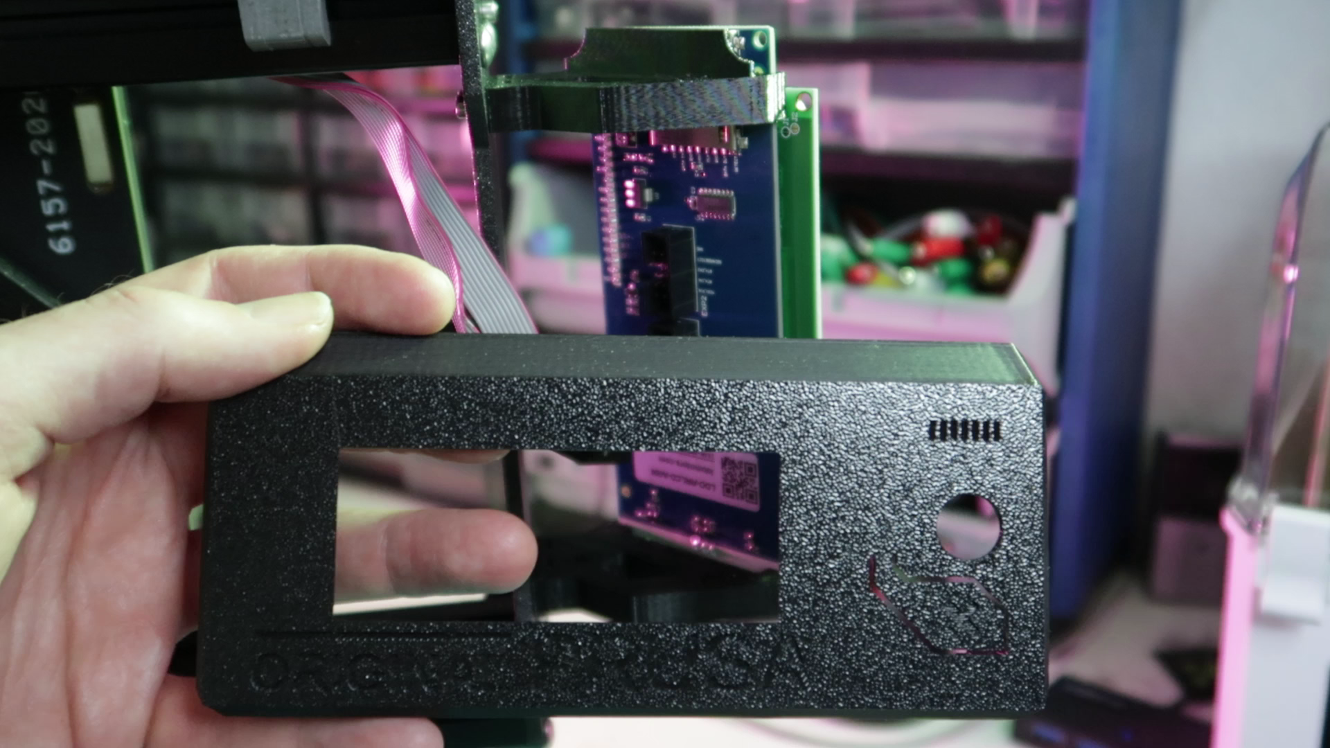
Remove the display module by first sliding it down, tilting it outward and pulling it up and out.
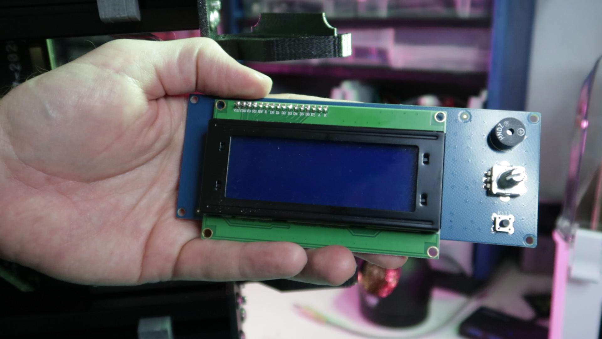
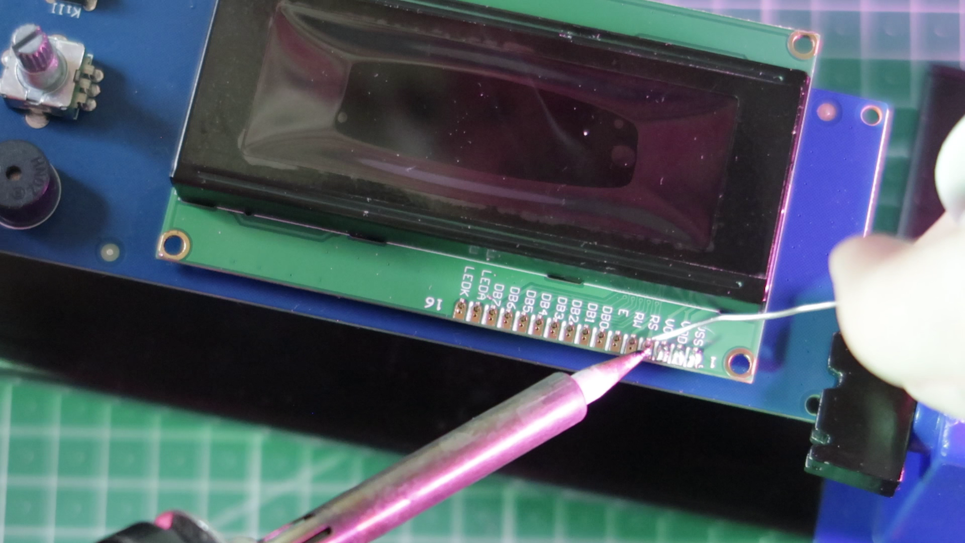
Upon examination of the board, you will see 16 header pins connected to the original LCD. These are the pins we will need to de-solder.
Separating the Boards
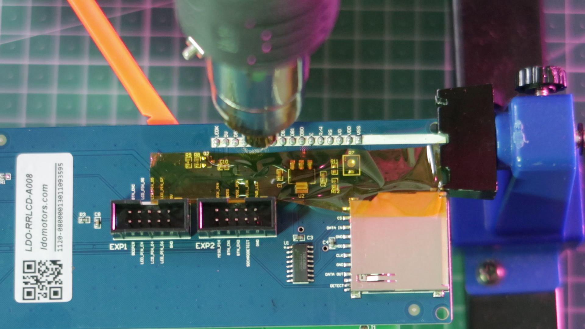
Secure the display module in a PCB vice if you have one. If not, desoldering the display could be more difficult. In my first attempt, I tried removing the boards with my hot air station. After adding an ample amount of flux and turning my hot air station up to 370°, I didn't have any luck melting the solder. I also used pulled on the header pins with a plastic spudger. I probably could have removed it if I had been more patient.
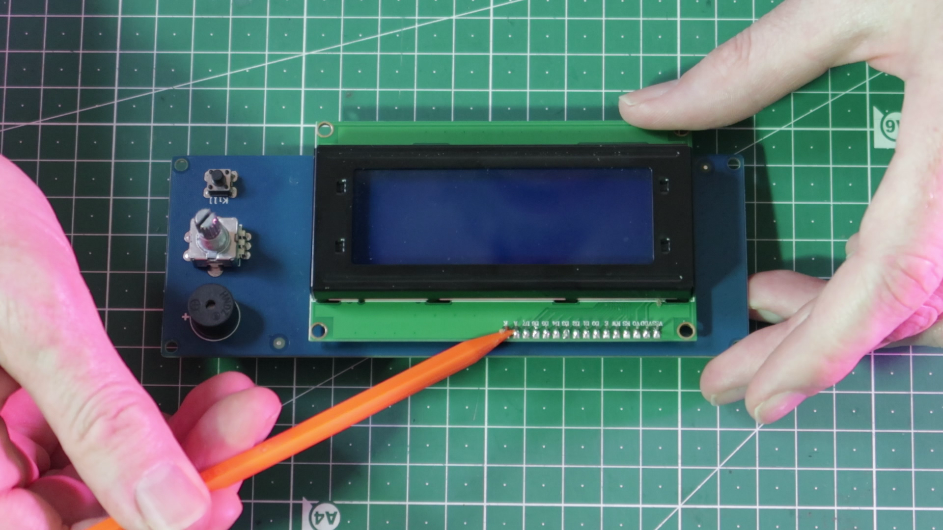
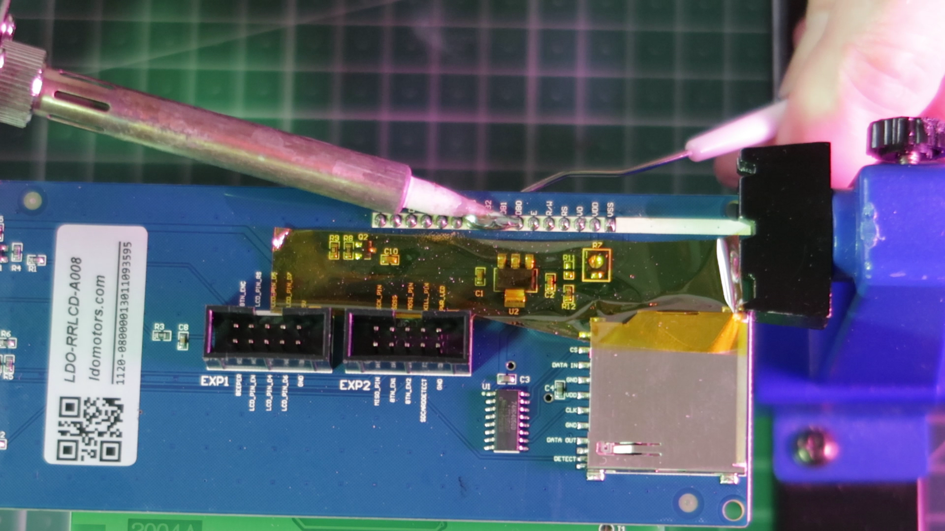
In my second attempt at separating the boards, I added low melt solder to the head of each pin and dragged my soldering iron tip back and forth over the connections. At the same time I used a dental pick to pull down on the boards keeping constant pressure. In less than a minute, I was able to separate the boards.
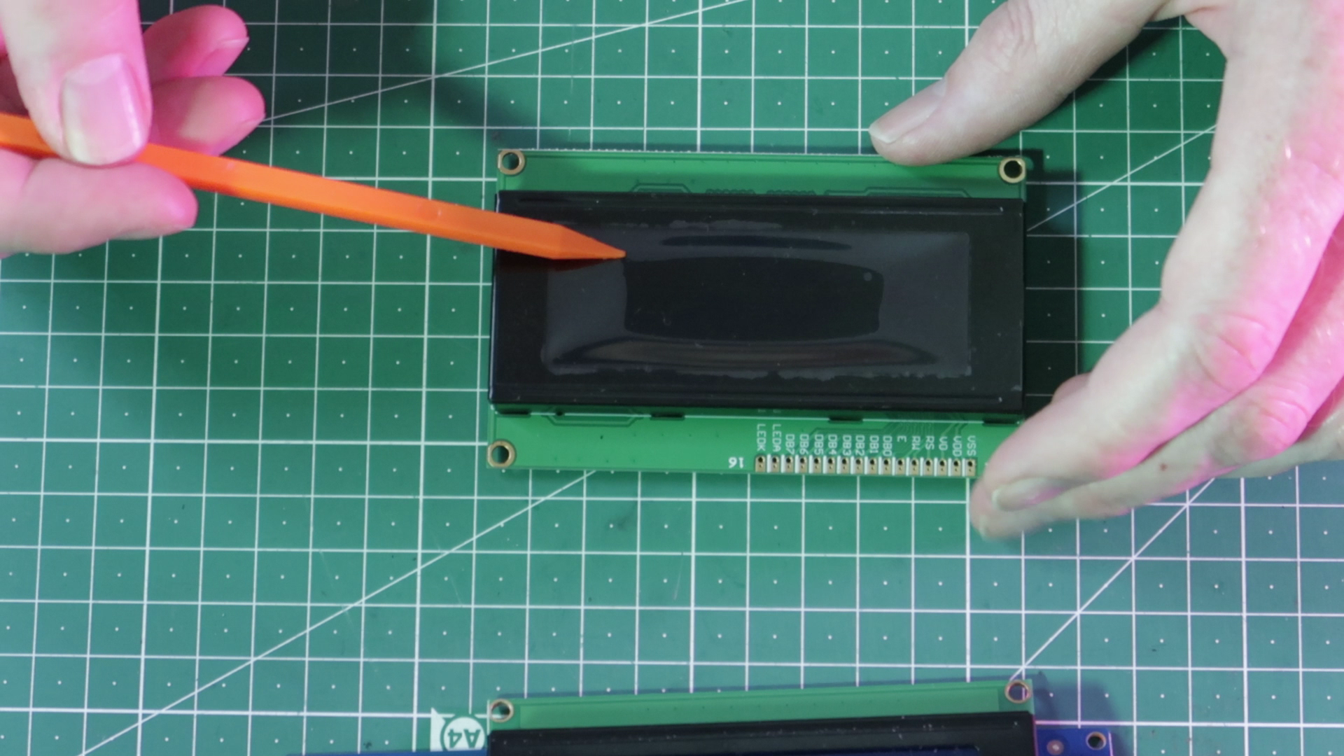
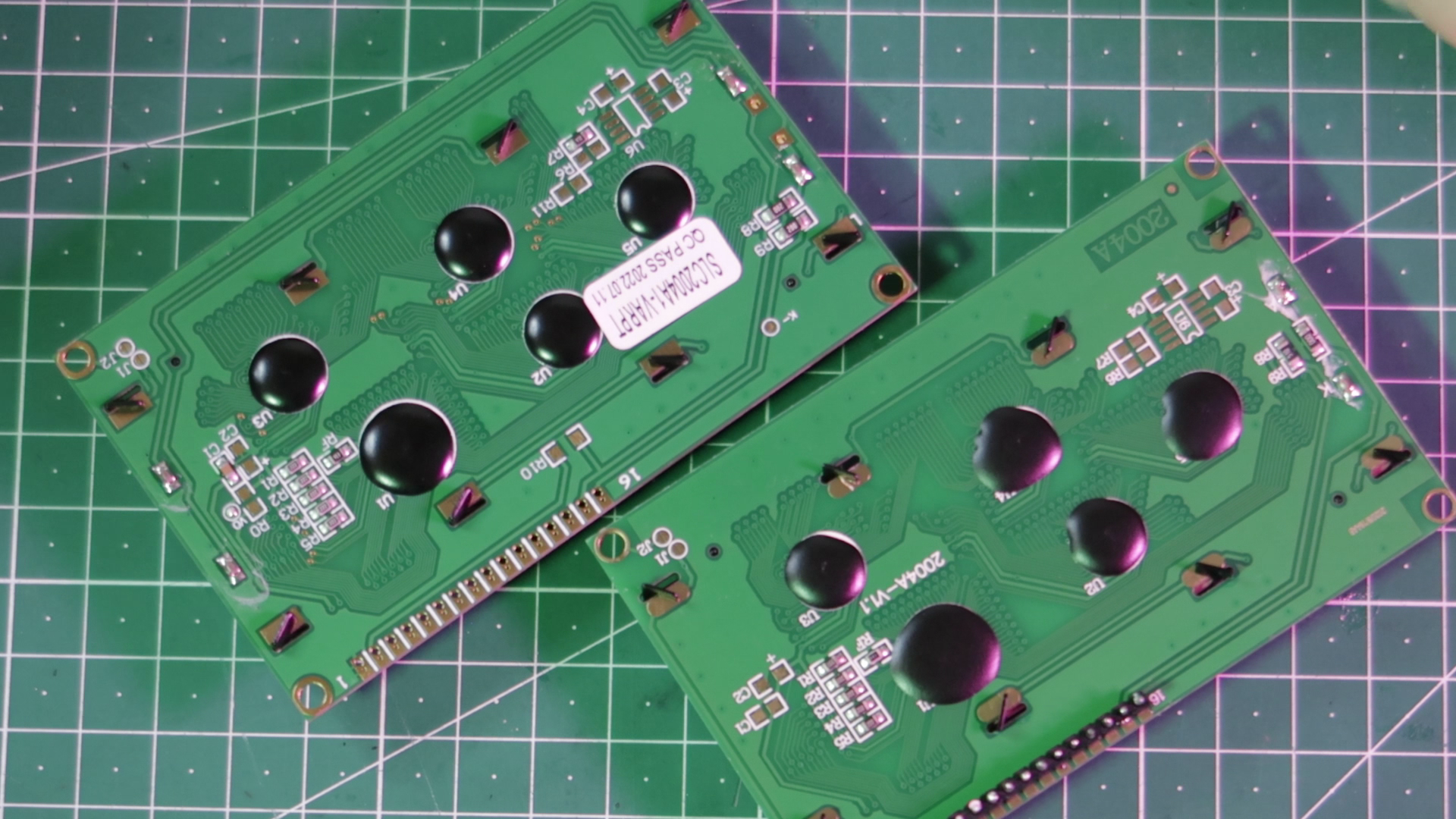
When comparing the displays, you can see that the pinout is the same. For my displays, I noticed the version numbers were different. The red display is a newer iteration than the original. This isn't a problem, as long as the pinout is the same.
Connect the new Display
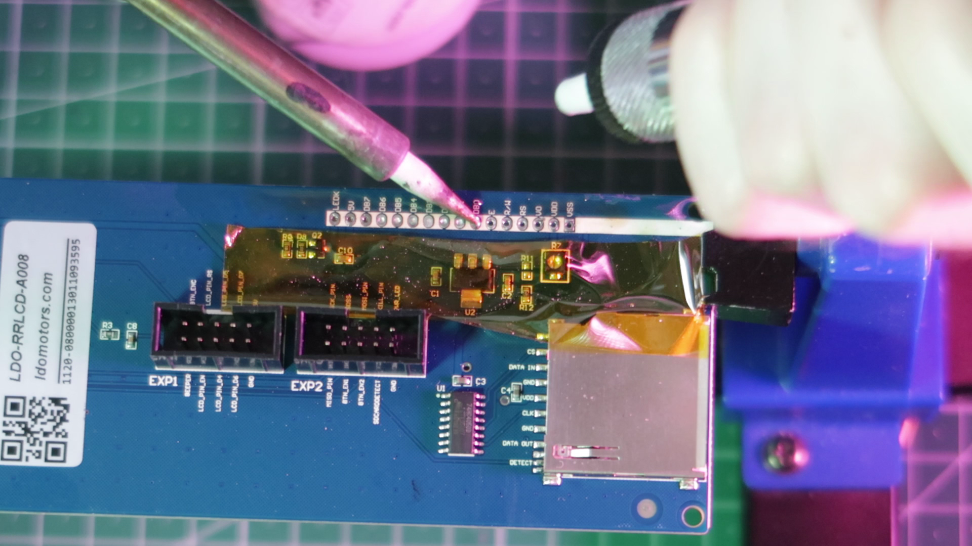
I cleaned off the old solder with a solder sucker and my soldering iron, then wiped off the flux in IPA.
Now, we can solder the header pins to the new board. Break off 16 pins from a pin header, insert them into the new board and solder them on.
Reassembly
To reassemble everything, just follow the disassembly instructions in reverse. Take special note to attach the cables to the correct sockets.
Final Thoughts
This simple, inexpensive modification adds a nice level of customization and brings a nice bit of color into your workspace. I have the black version of the Prusa MK3S+ and the red display scratches an aesthetic itch of making everything color coded.