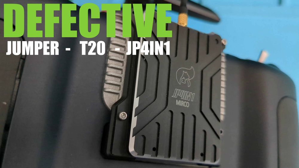
Troubleshooting Jumper T20 JP4in1 Micro Module
Synopsis
After watching and reading many reviews about the new Jumper T20. I decided to be an early adopter and ordered the ELRS 2.4 GHz version with hall effect gimbals[1]. I really like the form factor of the new Jumper JP4in1 micro module, and it fits perfectly with the radio. After receiving my package, I tried binding a few quads to the external module, only to be met with many difficulties.
Yes, I wanted the hall gimbals and not the the fancy-schmancy potentiometers ↩︎
Troubleshooting
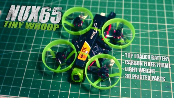
I first bound one of my tiny whoops using the FlySky protocol. I flew a few packs with the quad without problems. Afterward, I bound another tiny whoop using Frsky D. This is when my troubles started.
The quad would simply not bind. After half an hour of troubleshooting, I finally noticed that the module status for the external module would switch back and forth from "no telemetry" to "V1.3.3.0 AETR".
The module also got very hot, and I noticed that the battery was draining very quickly. Not good. Eventually, I got the whoop to bind, however the module would continuously lose connection then reconnect. After approximately 40 minutes of the module being on, my battery was down to 3.0V per cell and the module became completely unresponsive.
Assuming it might be a software issue, I checked out the troubleshooting page on multi-module.org and discovered that "no telemetry" means there is a problem with the module.
In this situation one of the following may be the cause
- The module is defective
- A somewhat common fault is bad solder joints on the 5-pin module bay connector.
I took apart the module and tested the module bay connection pins with a multimeter, only to find that the connections were solid.
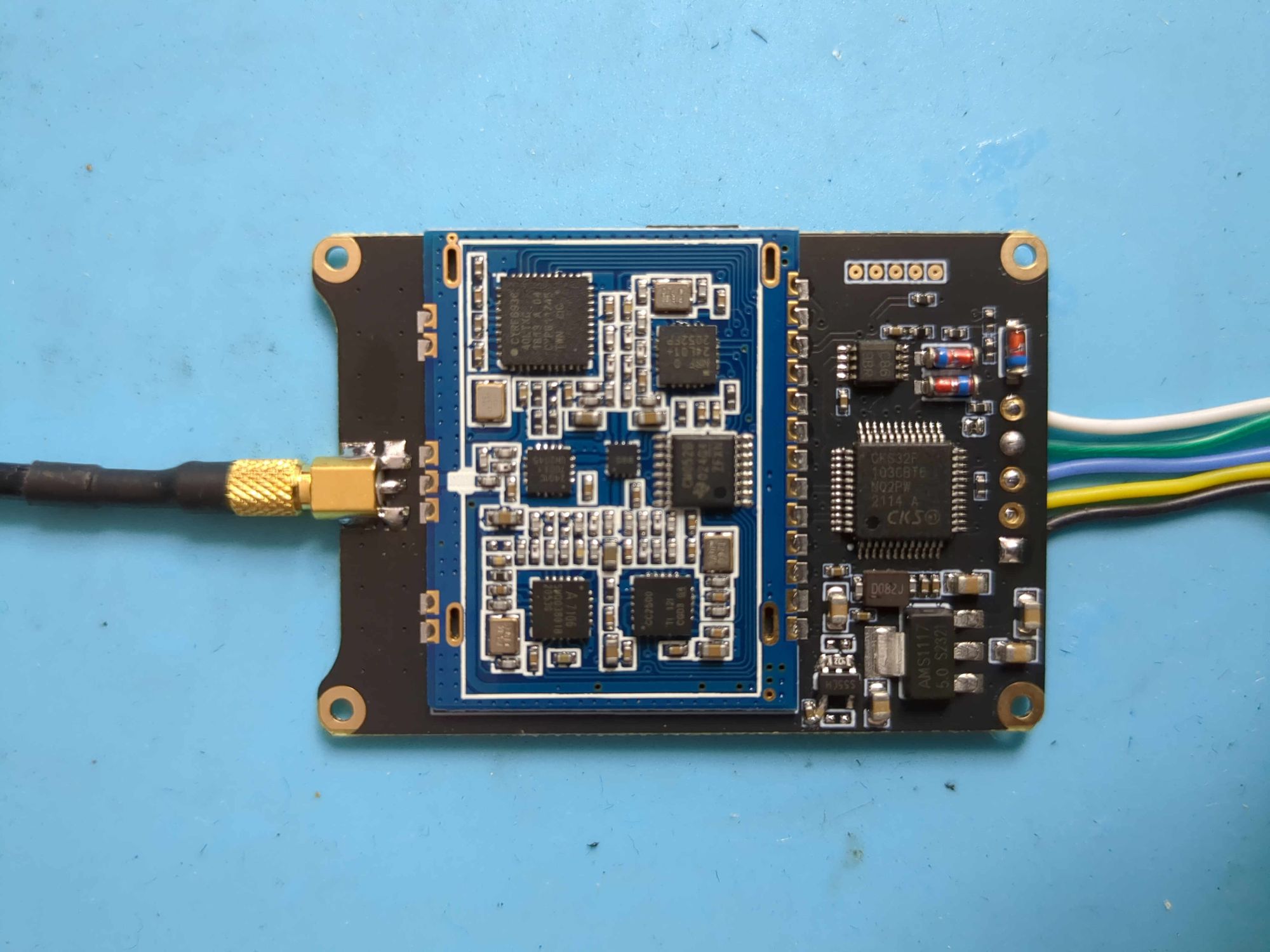
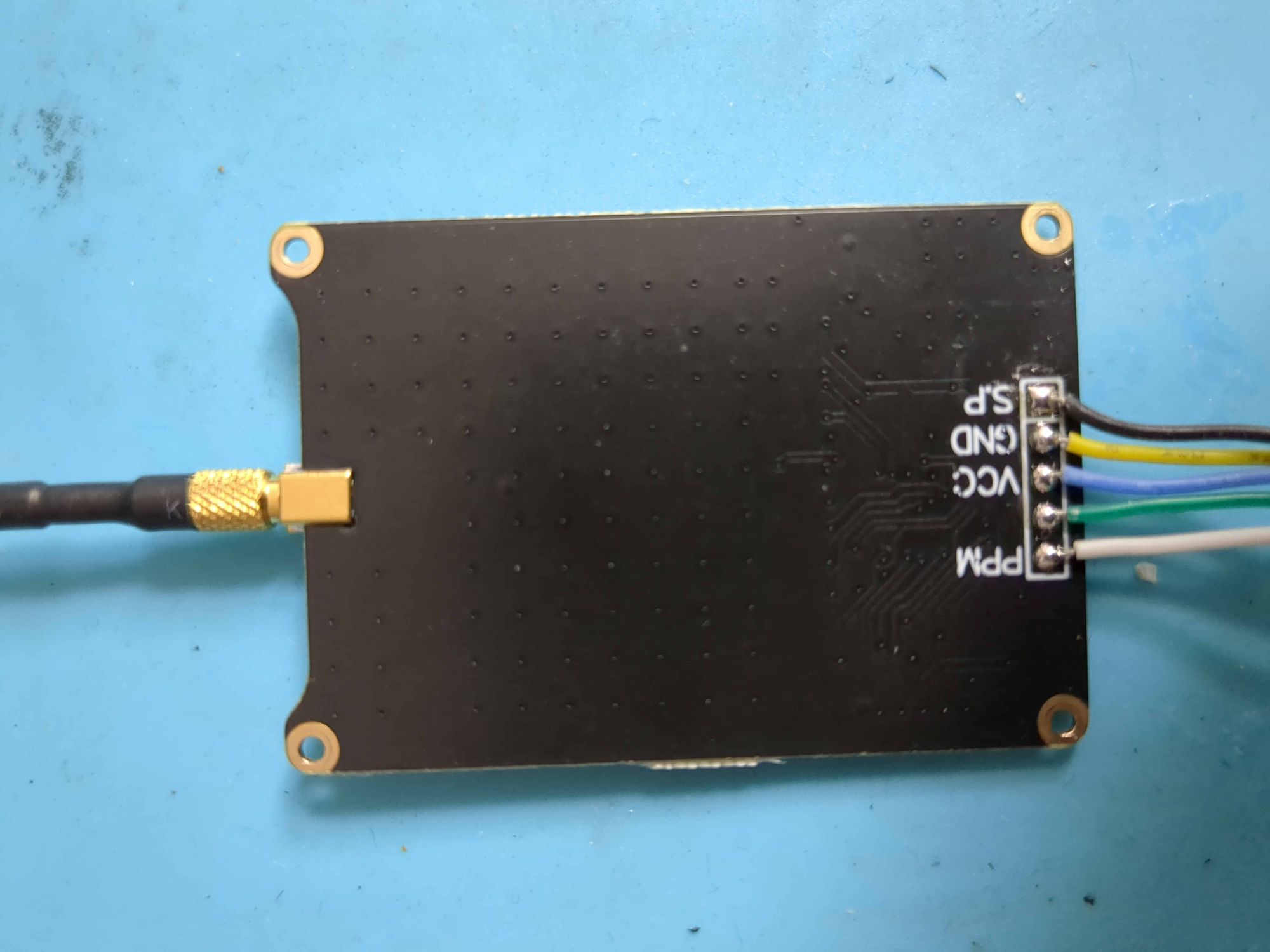
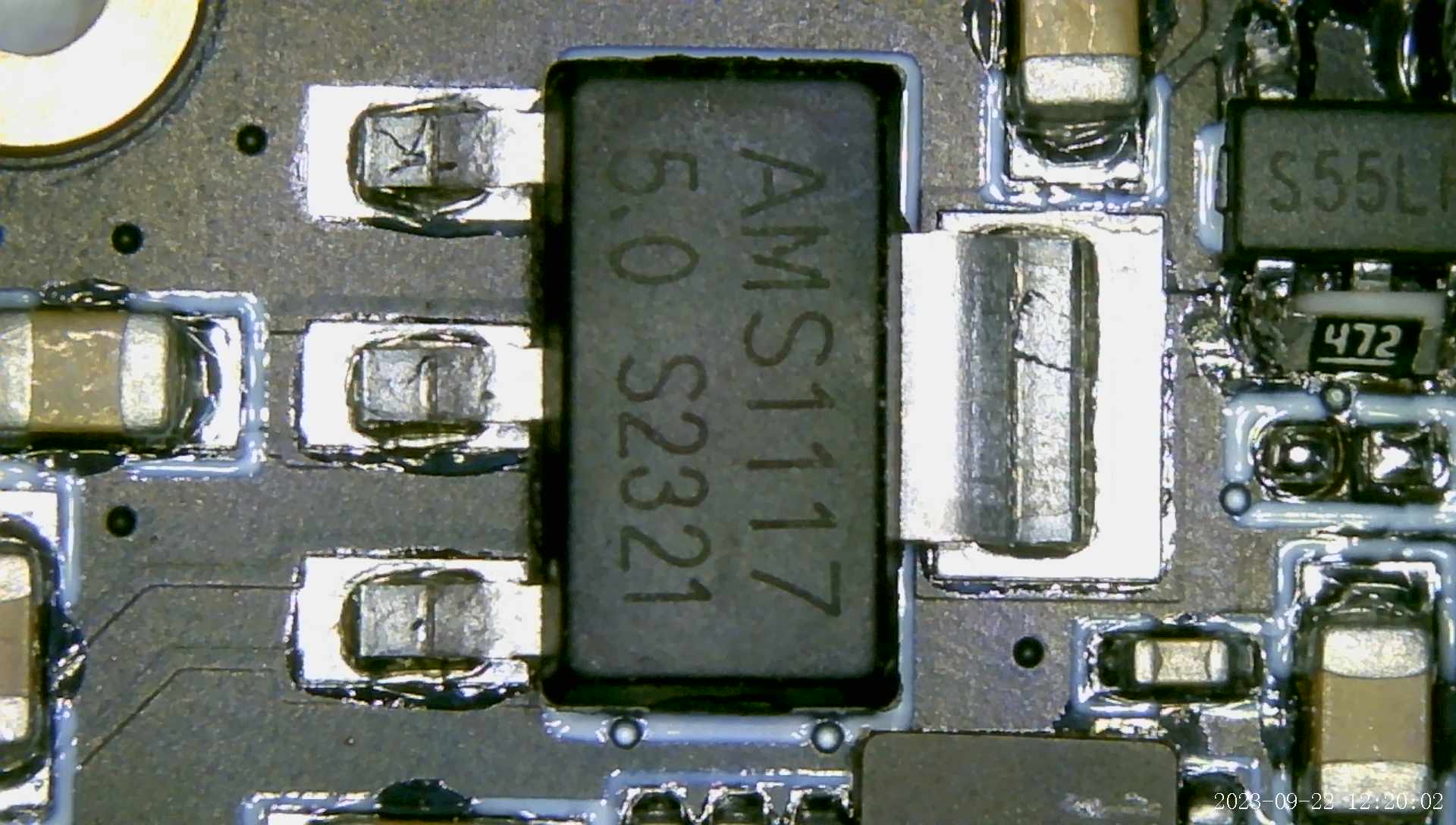
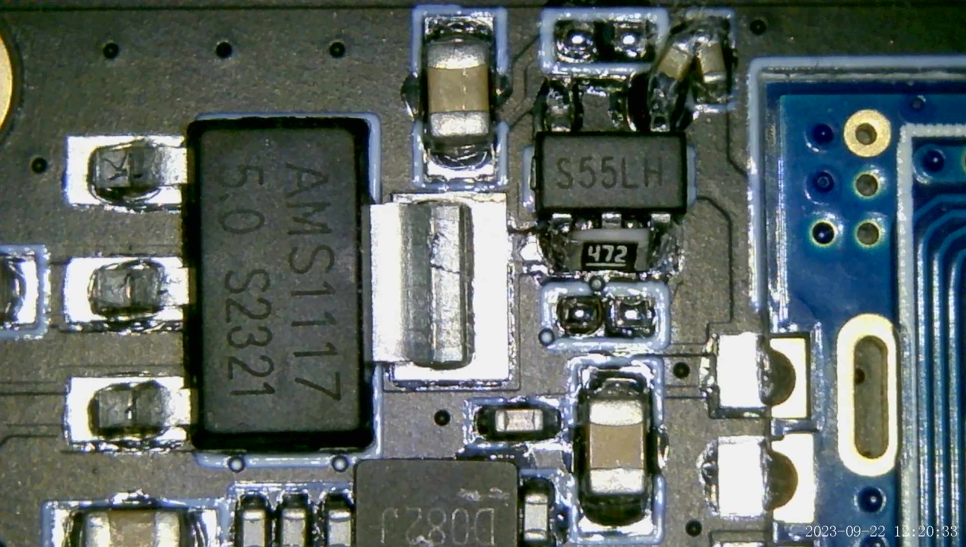
With the naked board in front of me, I did a visual inspection under a microscope and found nothing out of the ordinary. However, there was a hacky soldering job on one side. Any ideas?
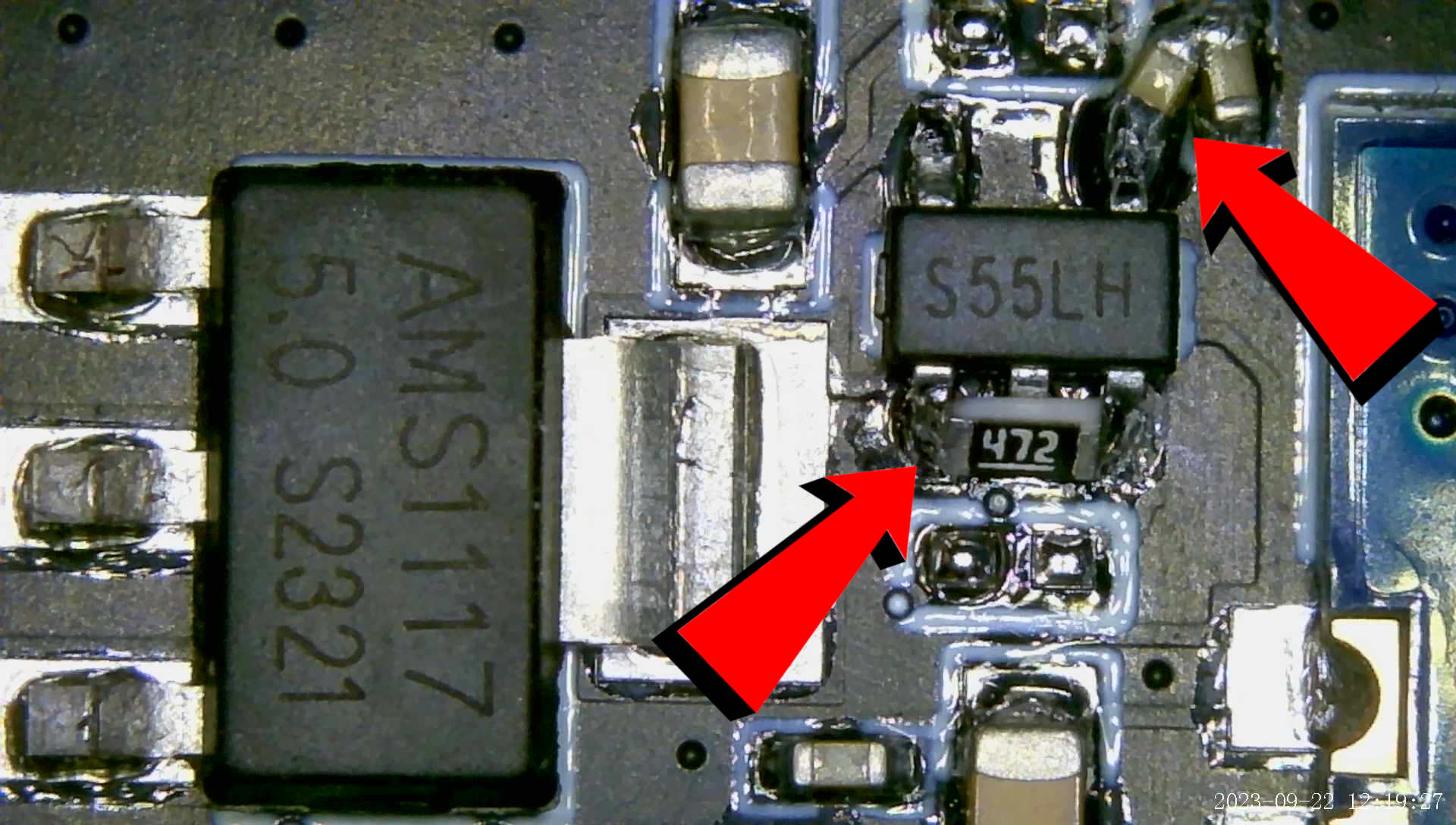
With my multimeter, all the caps on the board checked out, and I found no shorts. I then connected the module back to the transmitter, so I could locate the source of the heat. I don't have a thermal camera (yet), so this was hit-and-miss. Eventually, I located the component dissipating the most heat. It seemed to be coming from the AMS1117 voltage regulator:
My guess is that there is a short somewhere else drawing excessive power. What do you think?
Final Thoughts
The module looks and feels very high quality. The form factor is very nice, and it fits on the T20 like a glove. Unfortunately, I was unable to get this module working. Since I am strapped for time and have many other projects with higher priority, I'm not going to delve further into fixing it and will be sending it back. Let me know in the comments if you have had the same problem or if there is something I might be overlooking.