Nux65 Tiny Whoop Build Guide
Synopsis
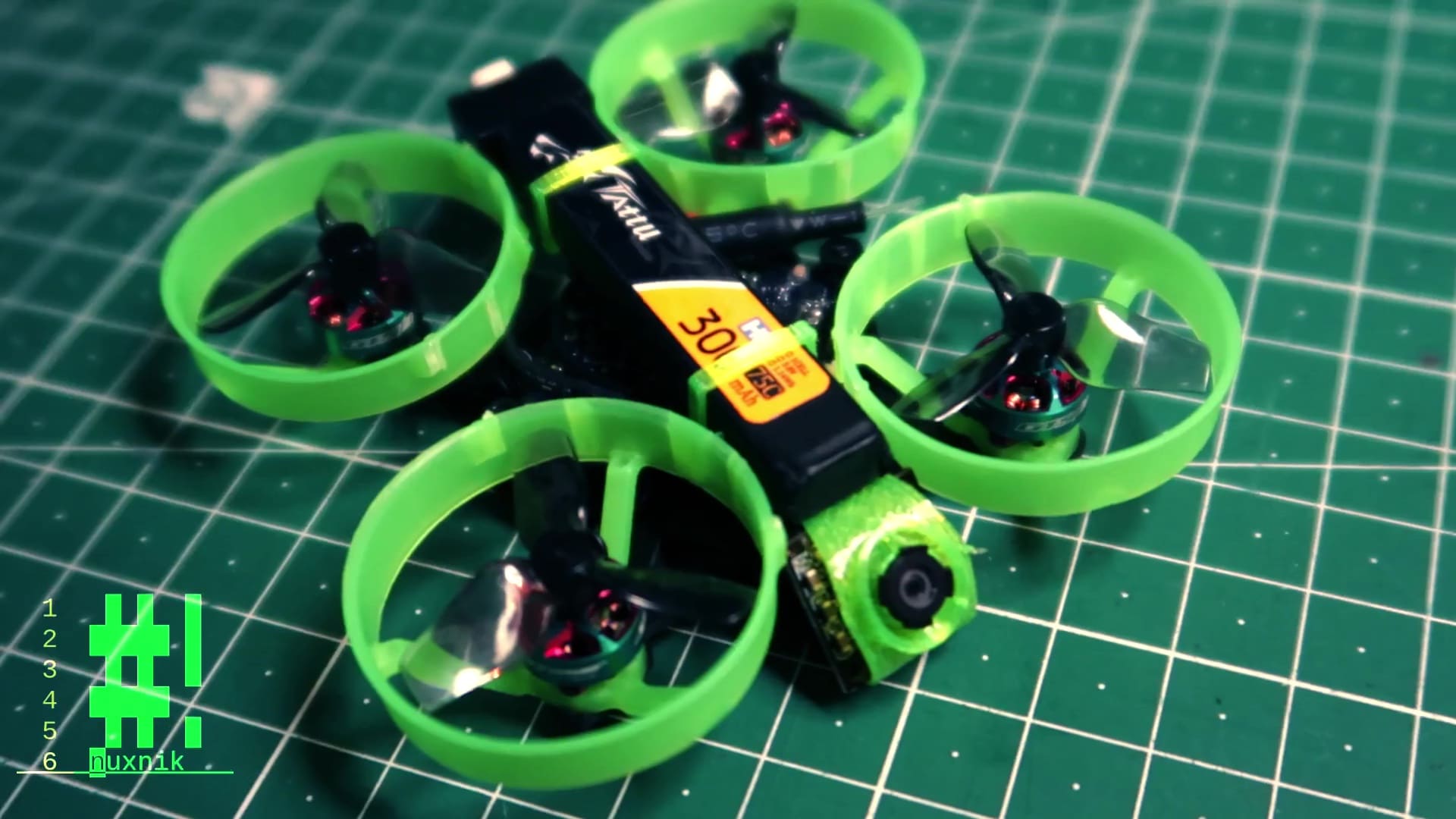
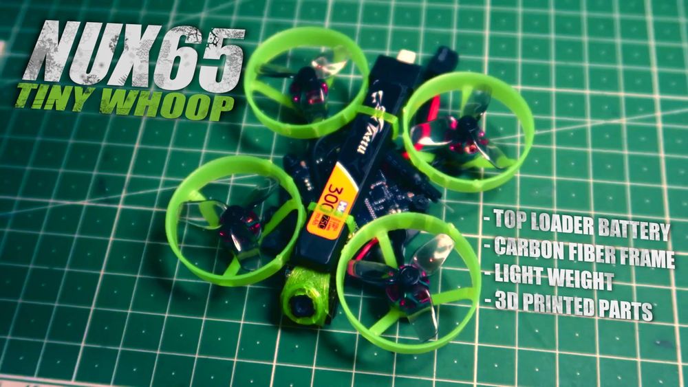
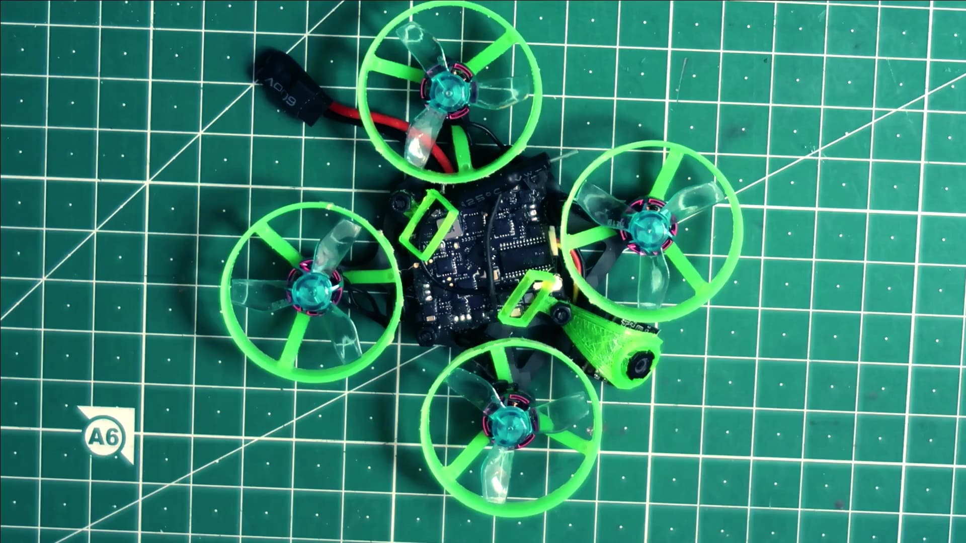
Let's build a lightweight tiny whoop with a top loading battery, carbon fiber frame, 3d printed parts and high KV motors. This project is a build guide for a 65 mm tiny whoop that was highly inspired by the Fractal65 by Fractal Engineering. This project was built in the “fractal whoop style”. In other words, this design is light-weight and stresses minimalism and robustness. However, calling it a “fractal style” whoop is not an accurate description. Therefore, for reasons of clarity, I will refer to this build as the Nux65. This project is a variant of a theme. I am not trying to copy Fractal Engineering designs, however, my design choices were highly inspired by them. It is my attempt at making something of my own, while at the same time paying homage to Fractal Engineering's creative design choices.
Required Tools
For this build, we will require the following tools:
- Soldering iron and soldering accessories
- Tweezers
- Helping hands
- Pliers
- Side cutters
- Heat gun or lighter
- 3D Printer
- Isopropyl alcohol
- Toothbrush
- BluTack
- Sand paper
- B-7000 Glue
BOM
Here is a list of all the materials I used to complete this project.
3D Printed Parts
The battery is mounted on top of the drone and sandwiched between the whoop rings. This build will require a three tiny 3D printed parts.
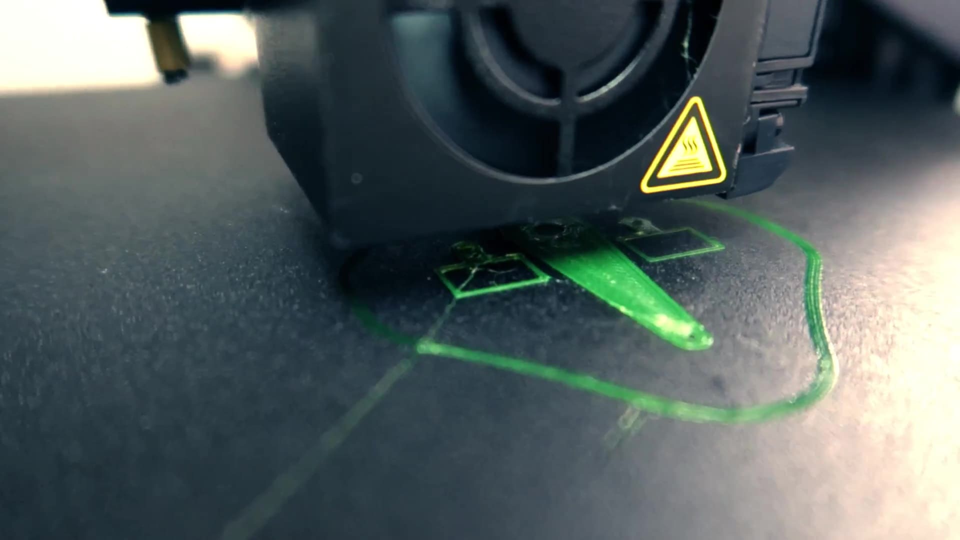
I have designed the files for this project in Solvespace. You can download and modify the original files from my GitHub repository. You can download the STL files from any of the following sites:
A “like” or “follow” on any of the above-mentioned pages would be greatly appreciated.
Preparing the Flight Controller
Before starting the build process, we will prepare the flight controller and add some upgrades. Please note that the following upgrades are optional. Some of these upgrades will add weight. Therefore, skip the next few sections if you decide you don't need them.
UFL Connector and Dipole Antenna
I have added this modification on most of my tiny whoops because it improves the video signal. The dipole antenna is detachable and delivers a clearer signal than the humble copper wire antenna. The biggest drawback is the added weight and is therefore a performance trade off. This is a simple upgrade, and for me, it is worth it.
Removing the Wire Antenna
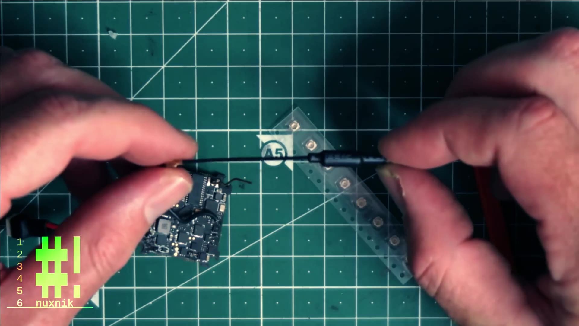
Before getting started, add a large tip to your soldering iron and set the temperature to 350 °C. Press the tip of the soldering iron to the back of the board where the antenna wire pokes through the PBC and pull out the antenna with a tweezer.
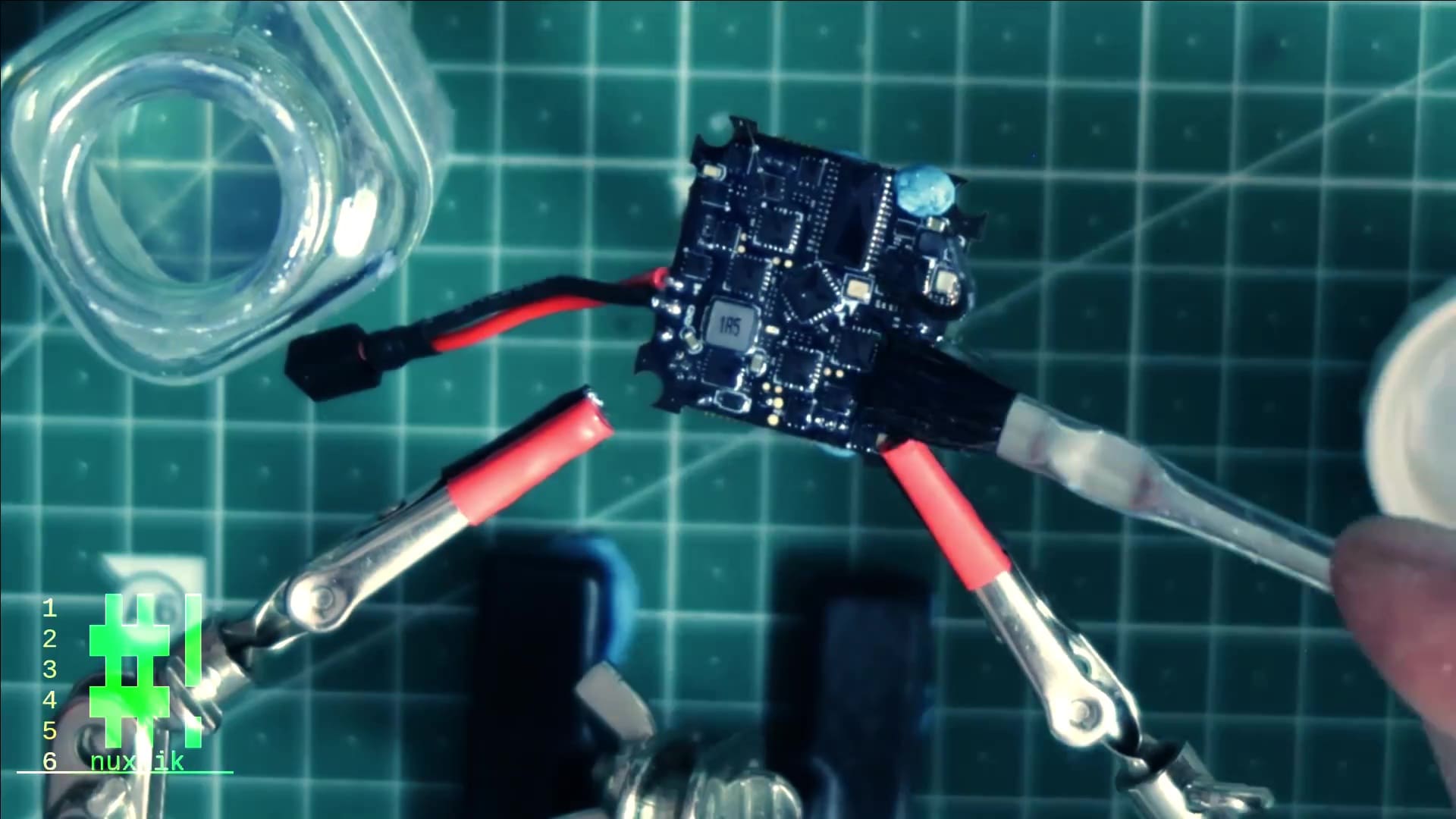
Mounting the UFL connector
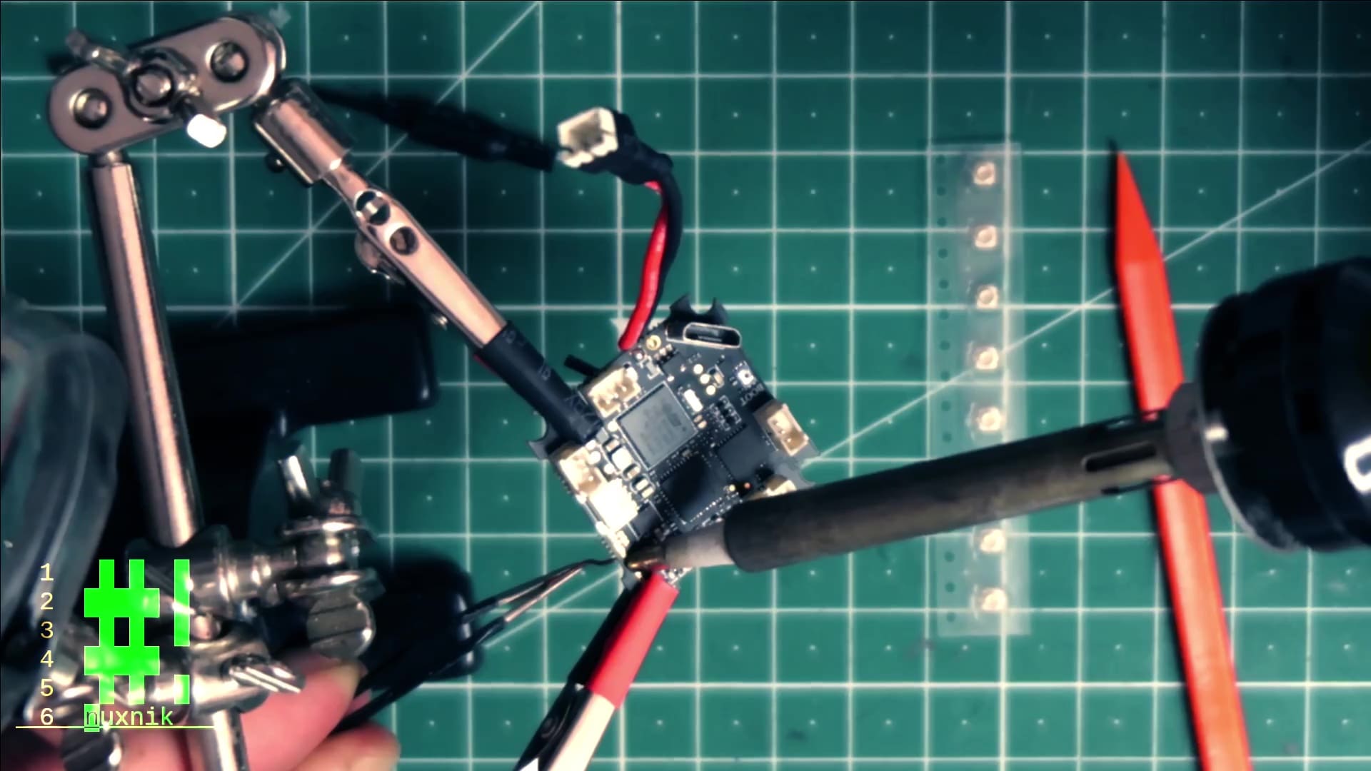
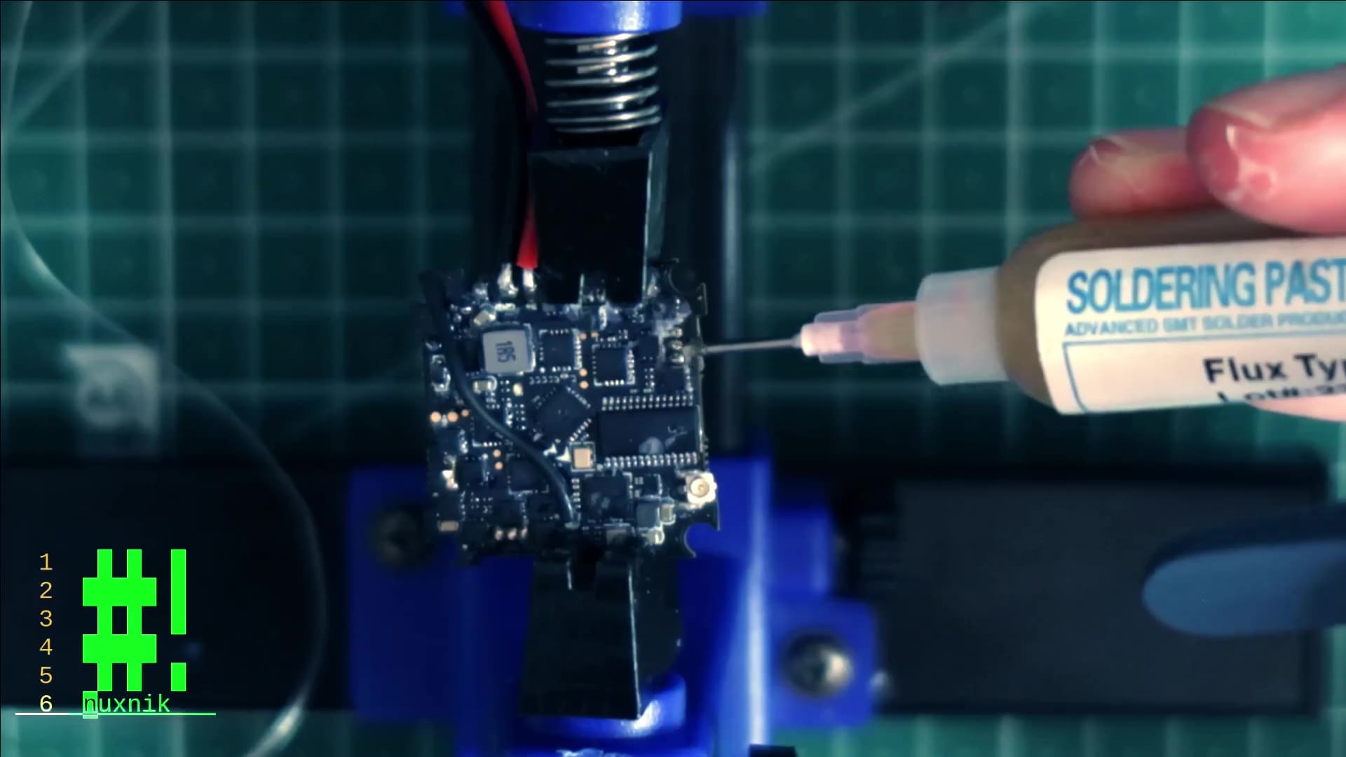
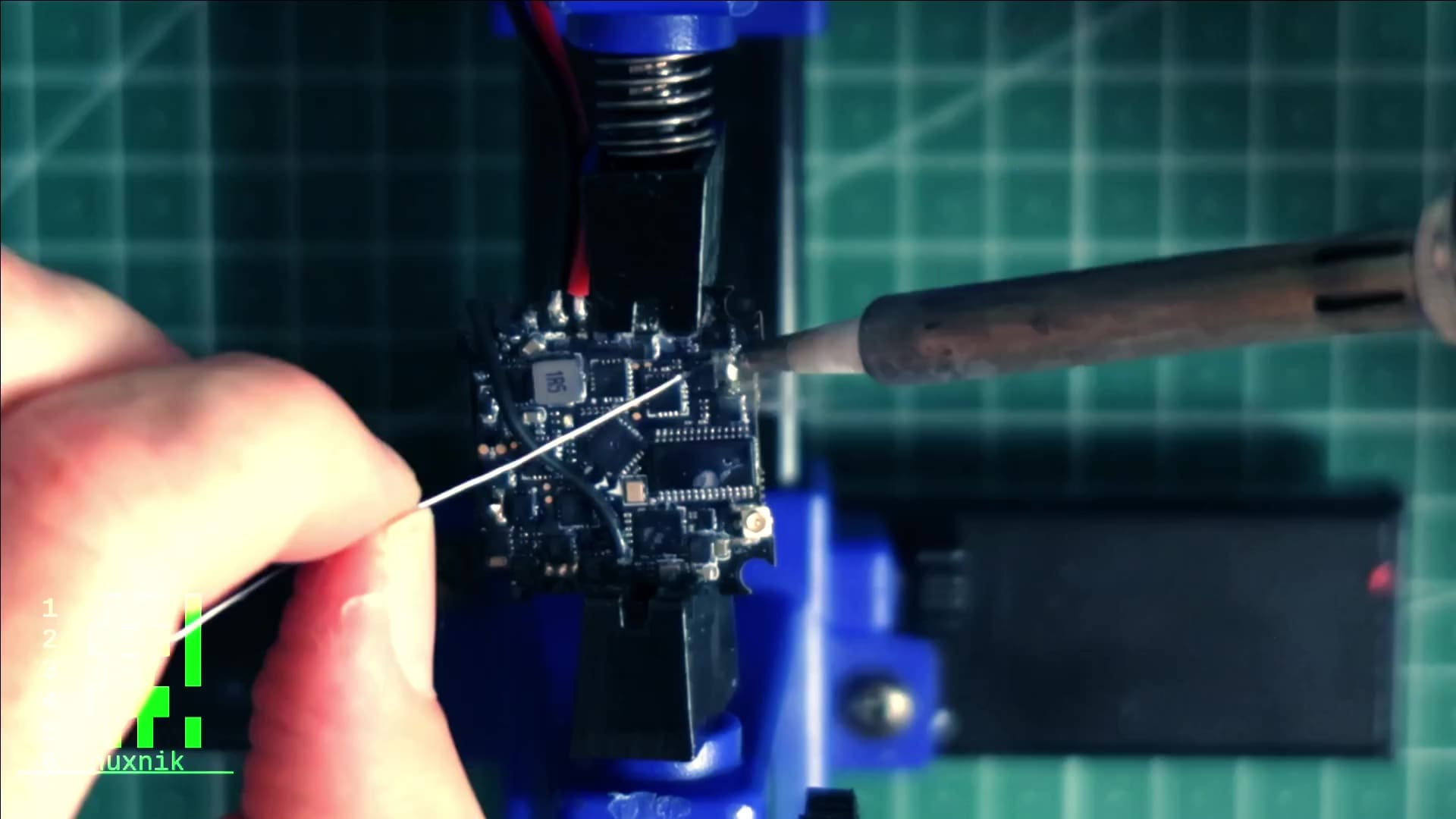
Add some flux followed by some fresh solder to the antenna pads of the flight controller.
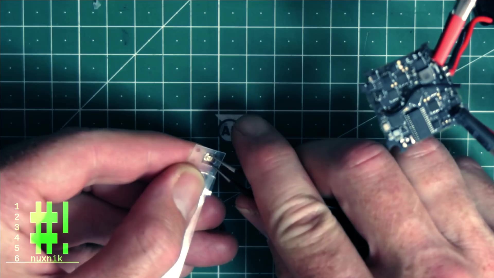
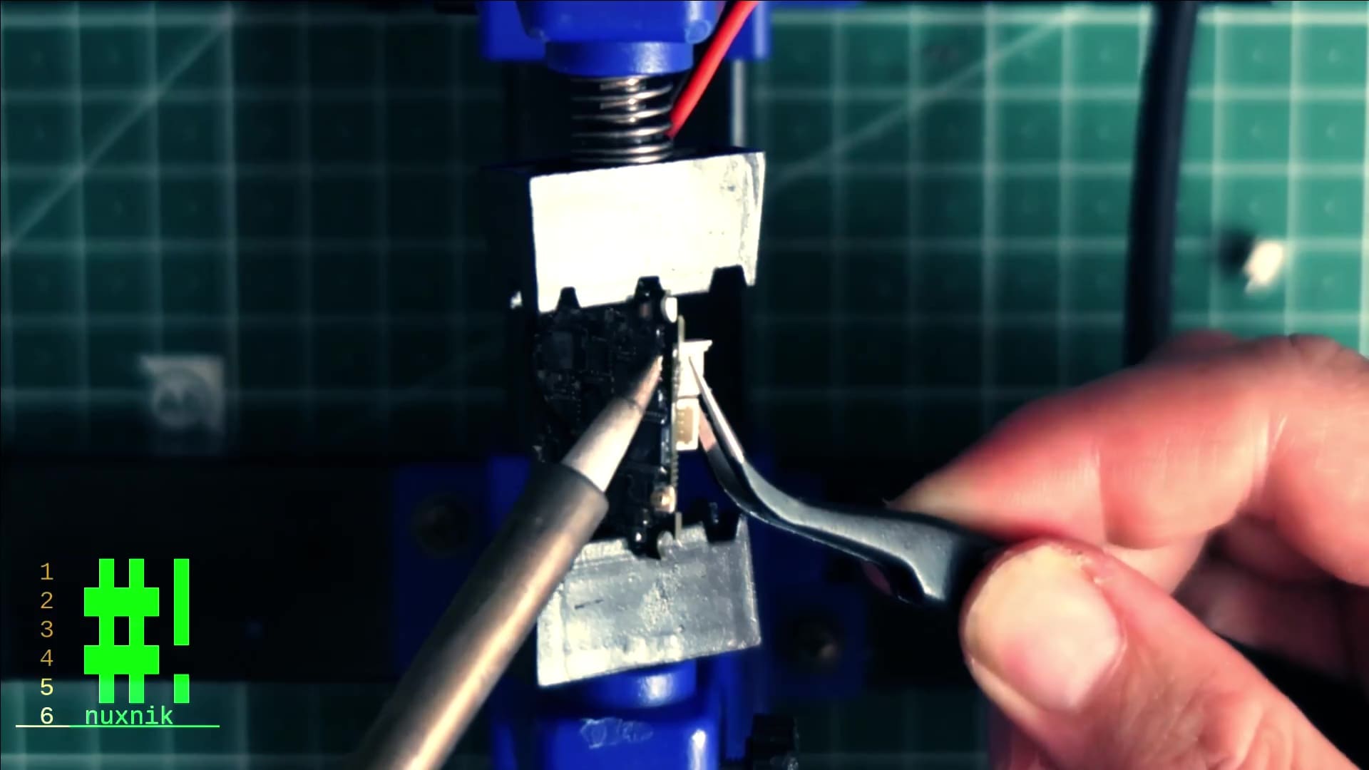
Hold the UFL connector with your tweezer next to the ground connection on one side of the solder pad.
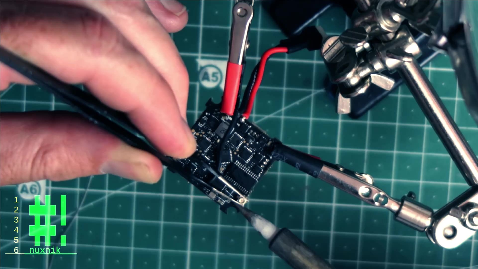
Melt the solder onto one side of the connector. This will anchor it to the board. Repeat the same process on the other side.
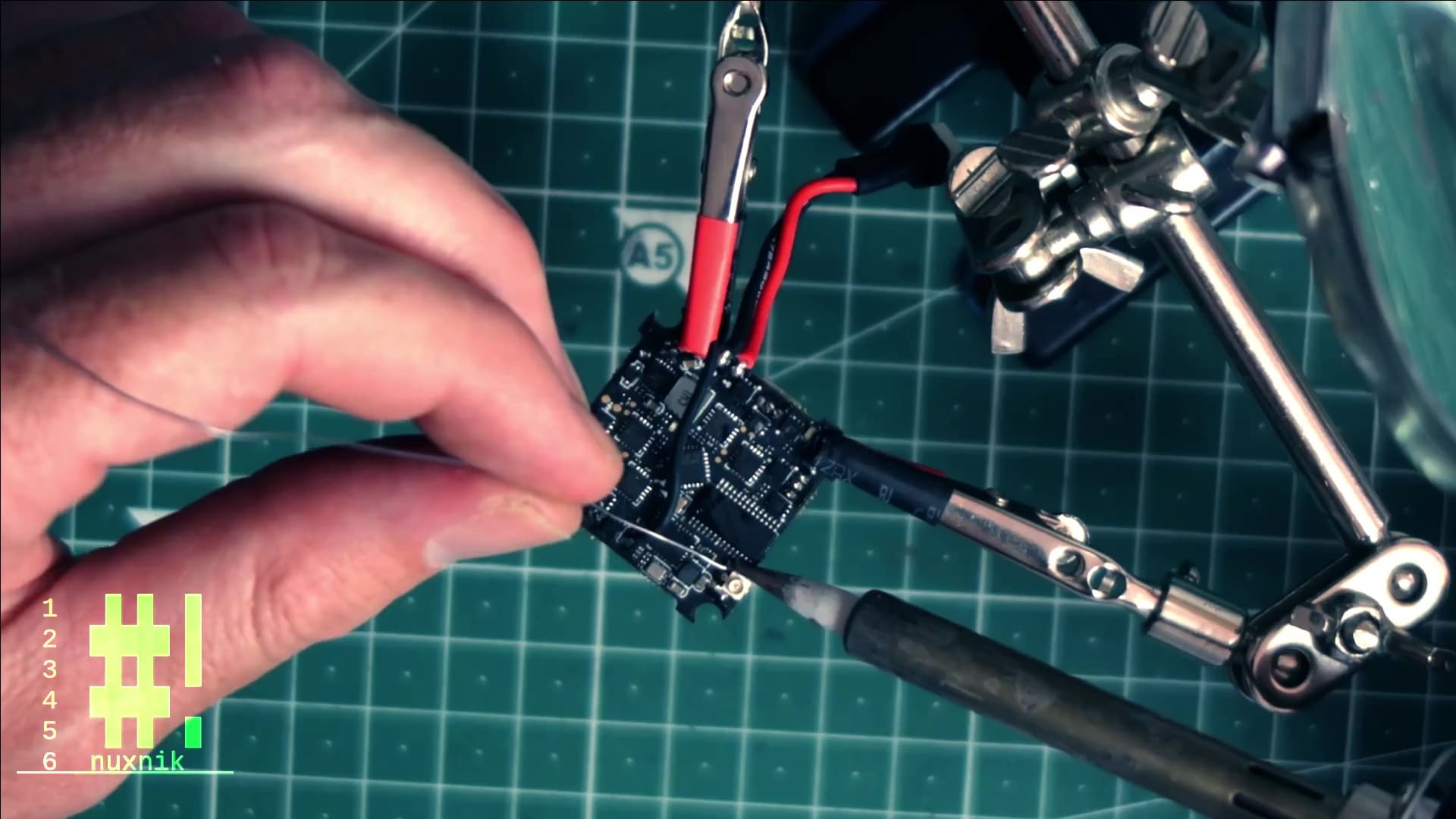
As a last step, connect the live element of the antenna.

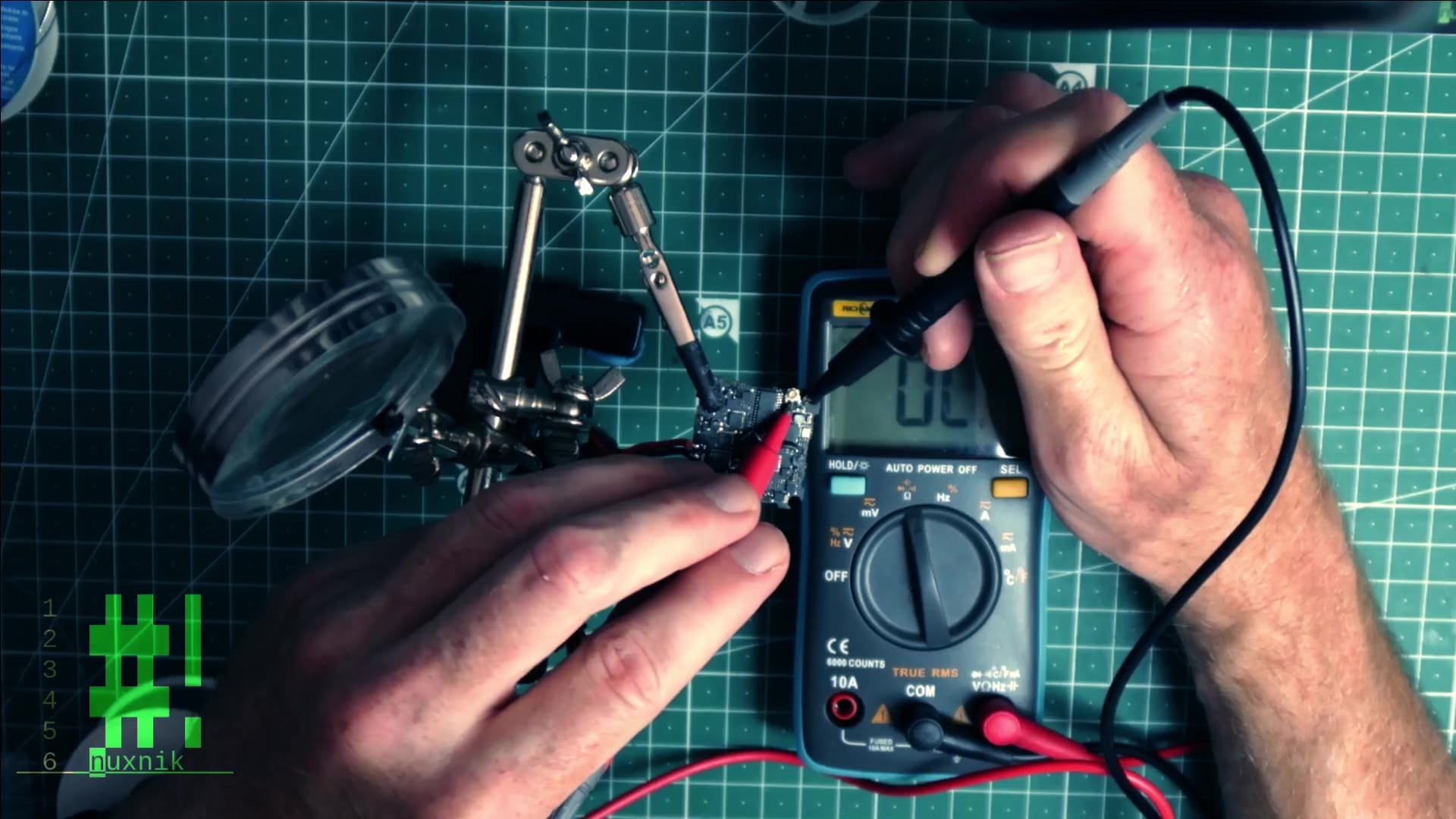
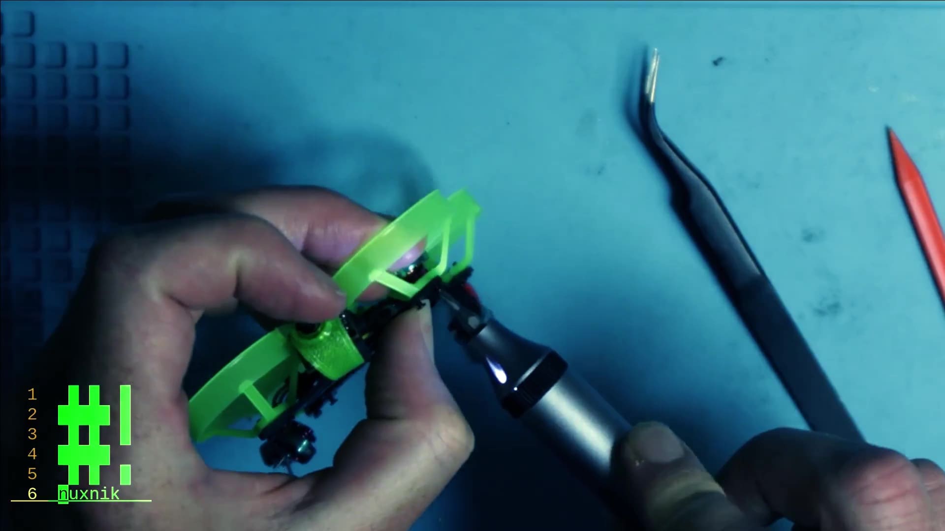
Before continuing, make sure that the connections are solid. With your tweezers, pull on the connector from different angles to tests for loose or unconnected solder joints. Next, set your multimeter to “continuity mode” and probe the connector to make sure that the connections are not shorting out to one another. These checks are very important. If the connections are not solid or shorted, you will fry your video transmitter.
A30 Female Connector
I recently wrote an article about switching to the BT2.0 connector and why it is better. Ironically, I discovered the A30 connector a week later. The A30 connector is essentially the same as the BT2.0 with a minor change. Both male and female connectors are compatible. The benefit of this connector is that the design has been open sourced. I will be exclusively buying A30 connectors in the future due to the fact. For this project, I ordered a pack of 5 Flywoo connectors.
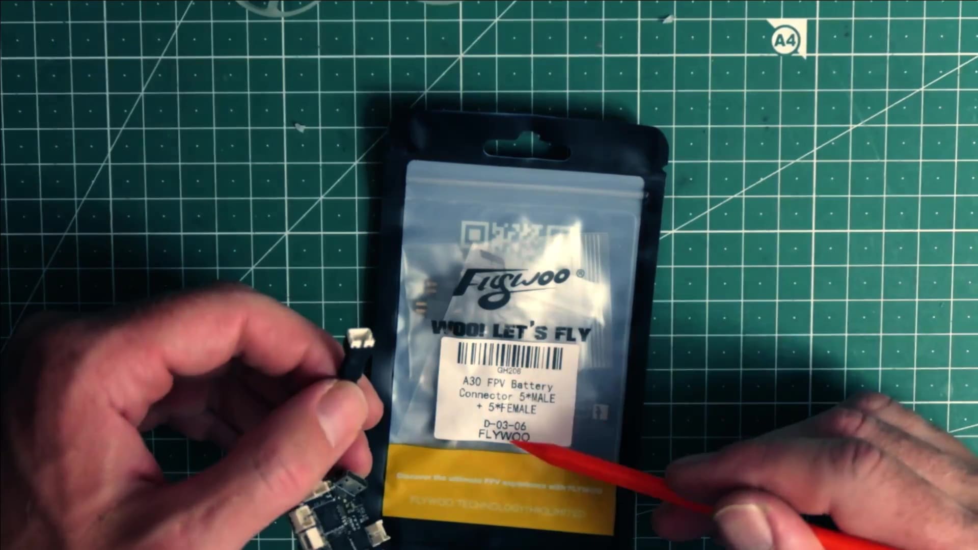
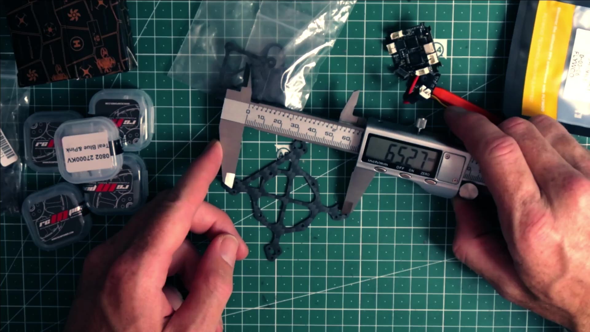
With some side cutters, remove the PH2.0 connector. Make sure your power leads are at least 5.5 cm long. If they are shorter, you will have a hard time connecting them to a battery. Should you replace them, make sure to use 20AWG silicone covered wire. Solder the wires to the connector. “Round is Ground” is a nice mnemonic device to help you remember the polarity of the BT2.0/A30 connectors. That means, that the rounded side of the connector is always the ground. Don't forget to add heat shrink tubing before soldering.
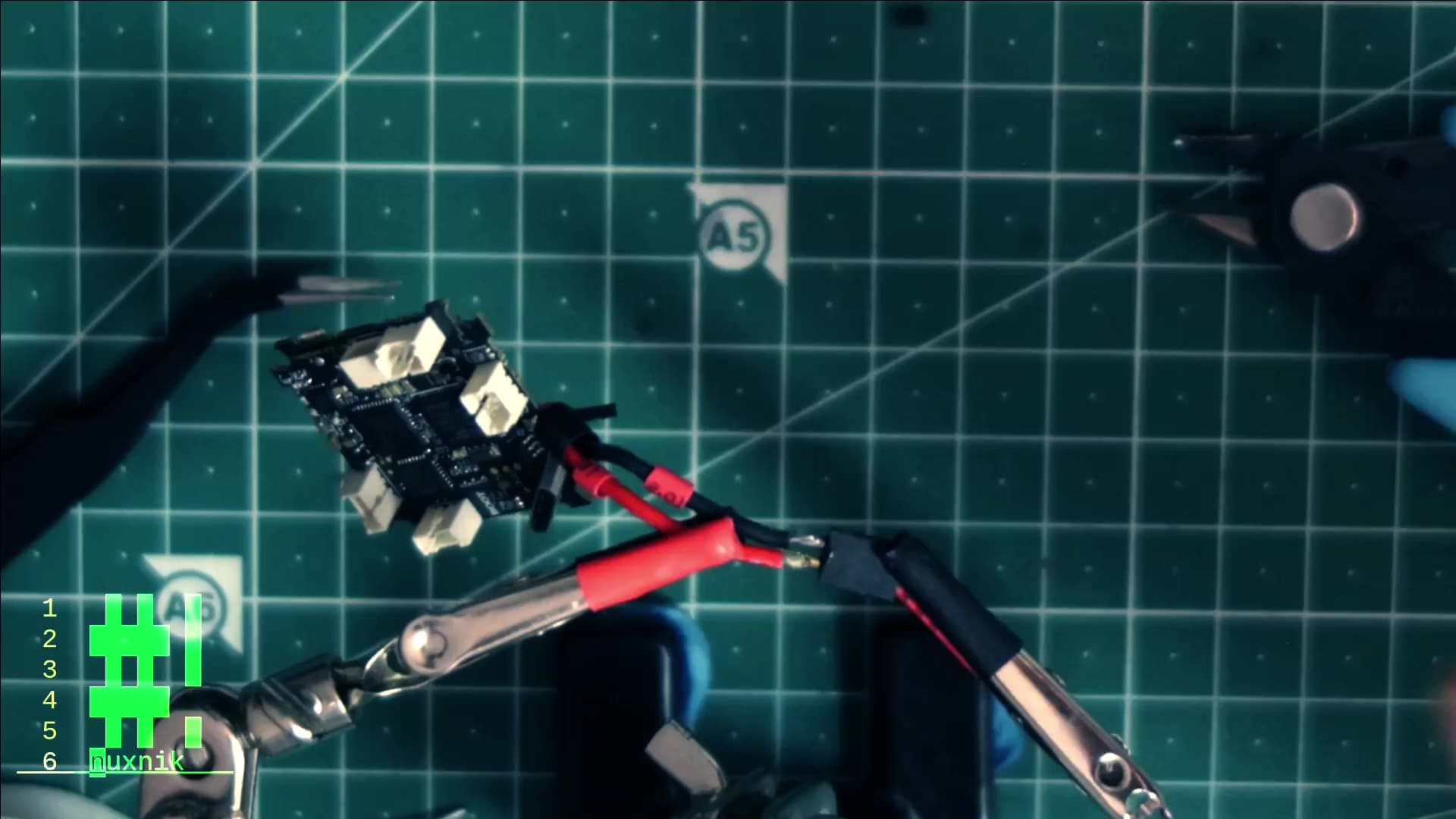
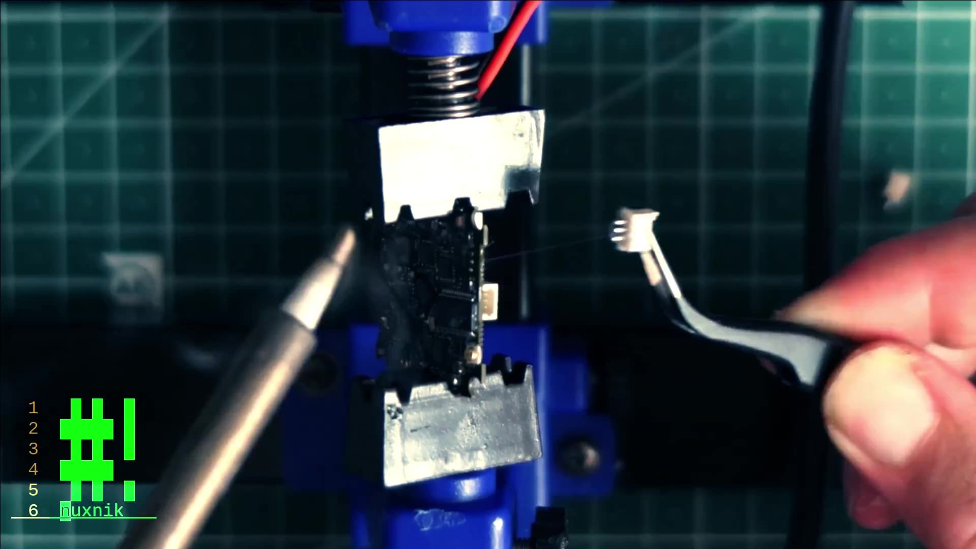
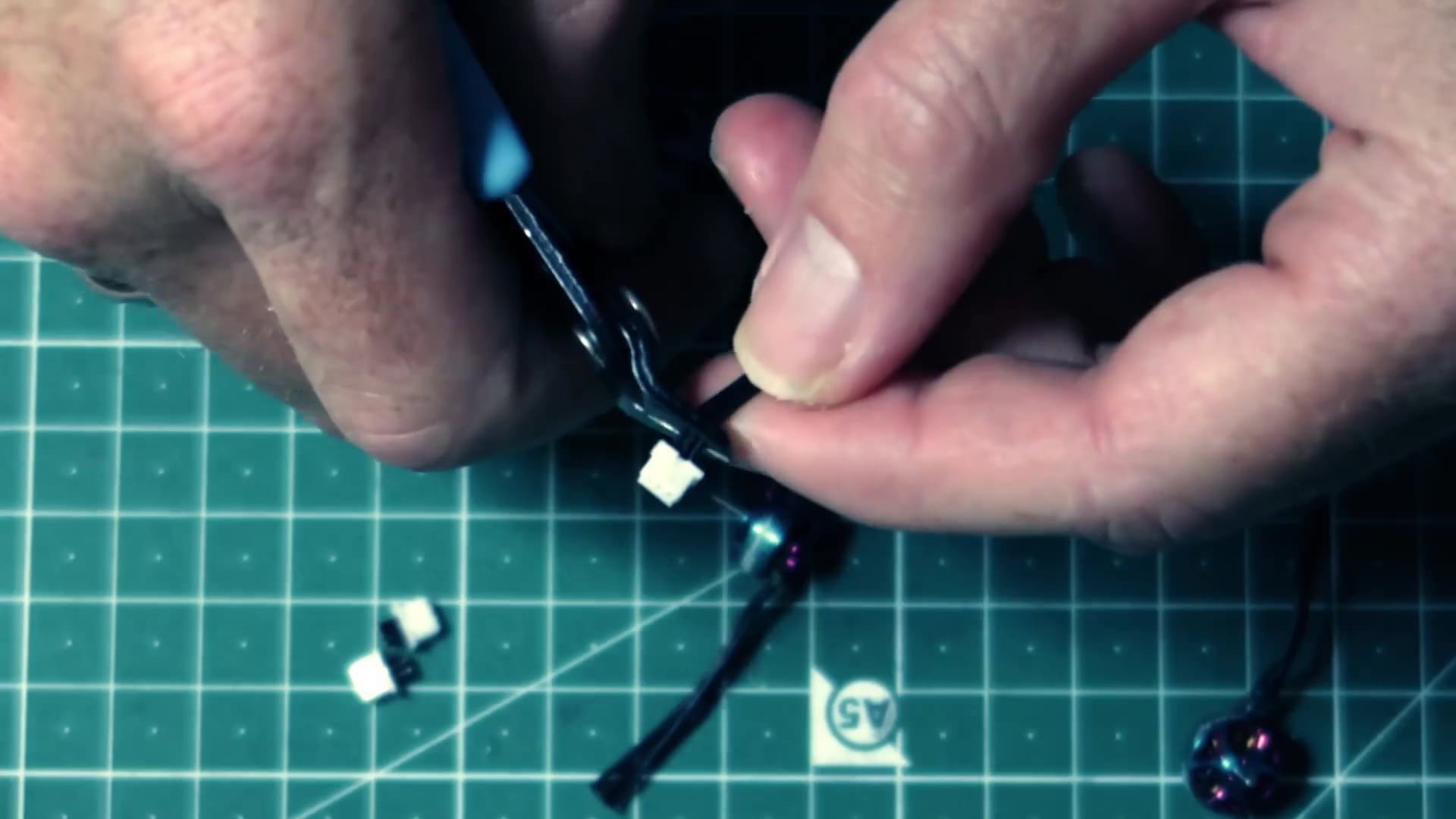
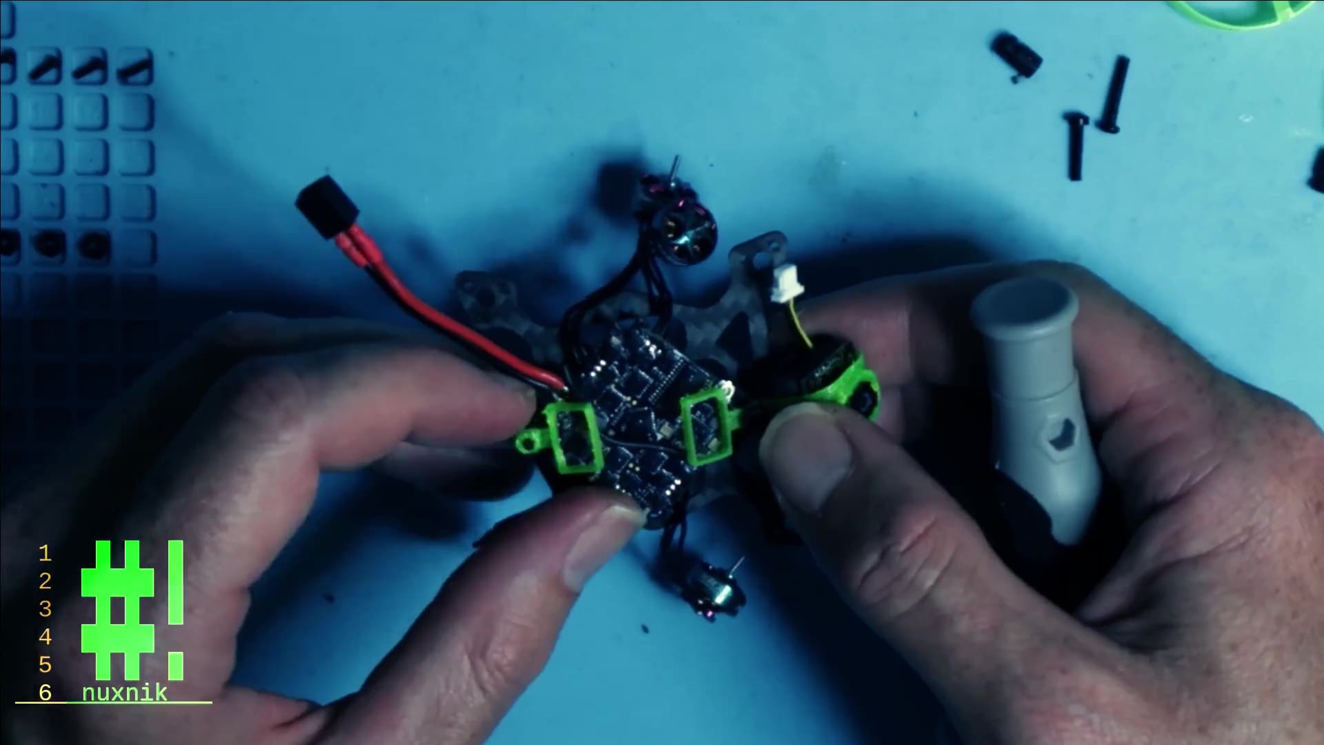
Remove Motor Plugs
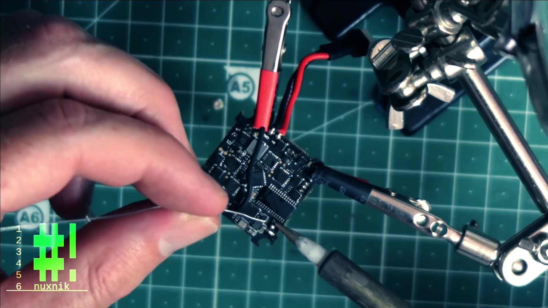
In order to cut down on weight, let's remove the motor plugs. This is a fairly straight forward process. Add flux to the motor pins.
Bridge all three pins on the backside of the motor plug with a thick blob of solder.
While holding the tip of the soldering iron to the solder blob, pull the plug out with your tweezers.
Repeat this process for the other motor plugs.
Silicone Conformal Coating
Adding silicone conformal coating is not necessary. However, keep reading, as it does offer some important advantages.
Water Resistance
Conformal coating protects your board from moisture. For most tiny whoop pilots, we fly indoors, so water is not much of an issue. Albeit, having conformal coating has saved my bacon a few times in the past – crashing into wet grass, puddles, sinks, toilets, or open drinking containers.
Added Shock Resistance
A second advantage of conformal coating is the added shock resistance. It creates a thick film over the flight controller's tiny SMD components, thus adding extra support for hard crashes. The components have small blobs of solder holding them onto the board that can be jarred loose. Let's face it, we crash all the time and need all the help we can get.
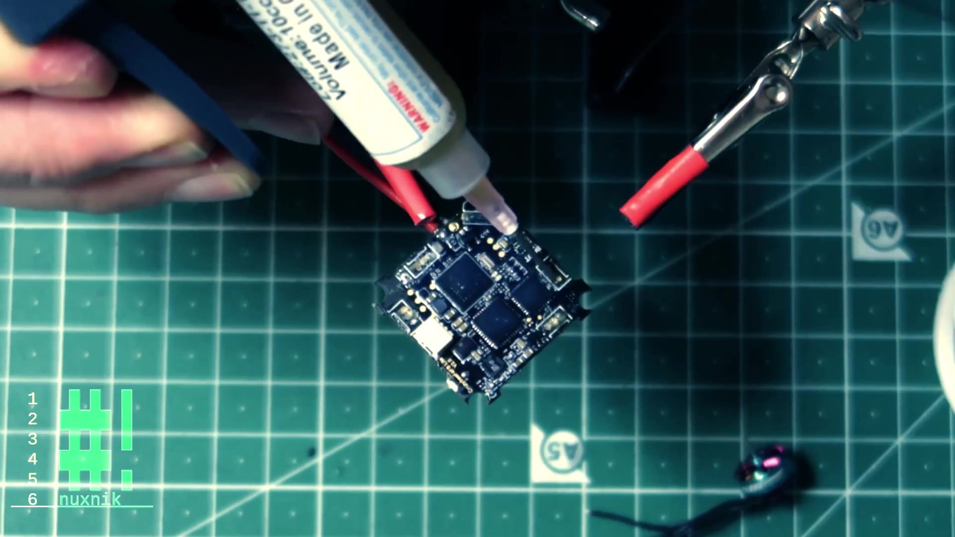
Applying Silicone Conformal Coating
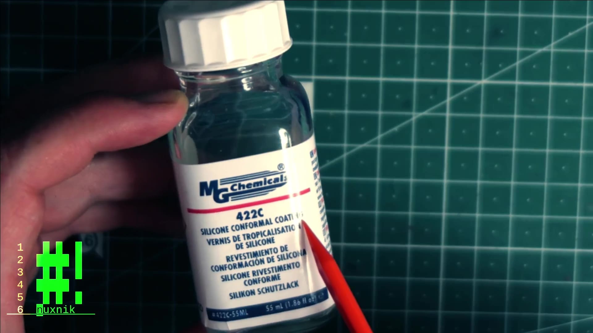
I have been using MGChemicals 422C Silicone Conformal Coating for years and am happy with its performance. One bottle will last you a long time. Before applying, remove dust and oil with isopropyl alcohol and a toothbrush.

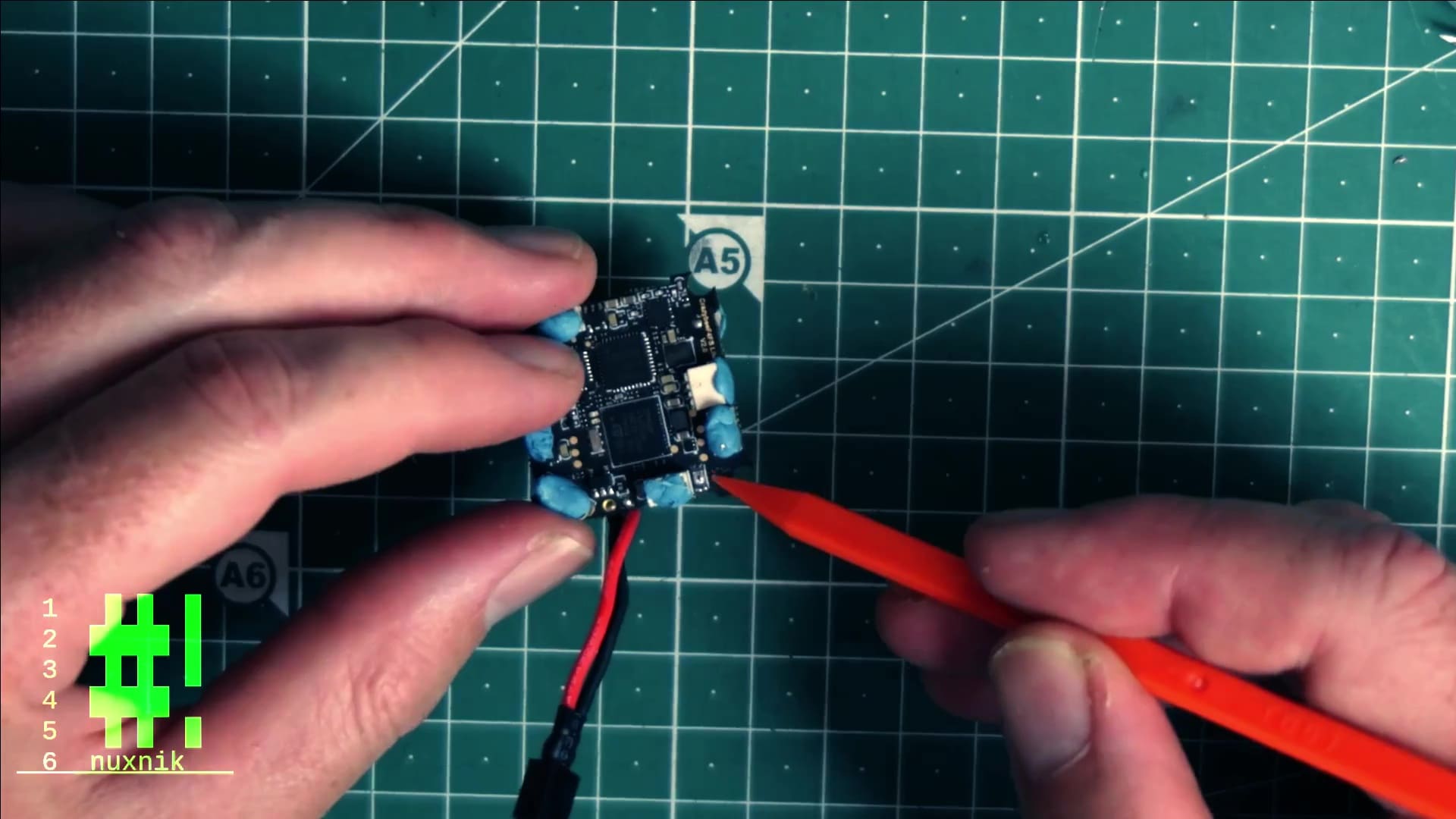
Conformal coating can insulate connections and cause your board to malfunction if you apply it to the wrong areas. Therefore, we will use Blutack and cover all the components on the board that should not be insulated. For this flight controller, I will be covering the following components with BluTack:
- JST Motor plugs
- JST Camera plug
- Boot/Bind buttons
- USB connector
- UFL connector
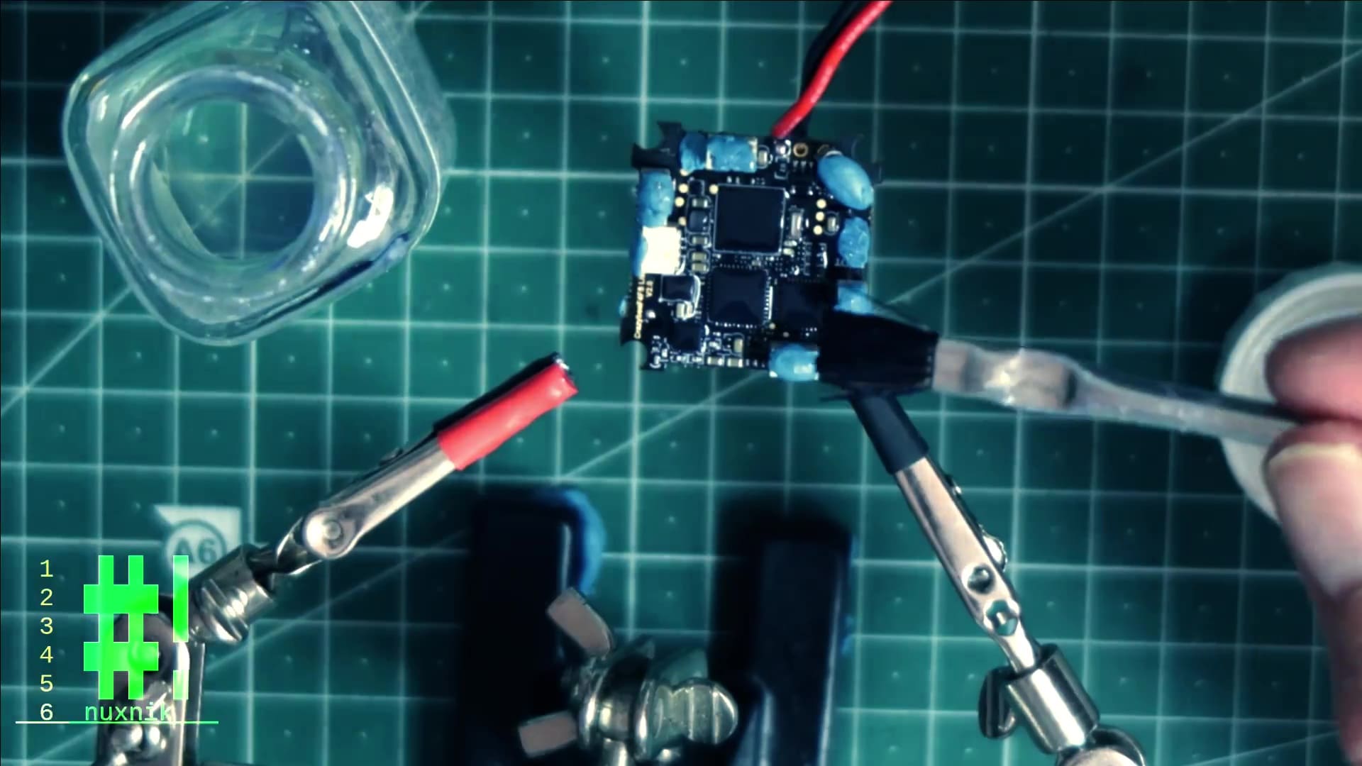
Warning: before getting started, use gloves and ventilate the room while applying. I did not use gloves for this build, and the exposure caused the skin on the tips of my fingers to flake the next day. Click here for more safety information.
Apply an even layer to both sides. It will harden under UV light, so set it into direct sunlight or use a UV light.
Connect Motor Wires
Connecting the motor wire is simple, but due to the small size of the board, it is tedious. Cut the plugs off of the motor wires.
Before connecting, apply a bit of flux to the motor pads and motor wires and pre-tin them with solder.
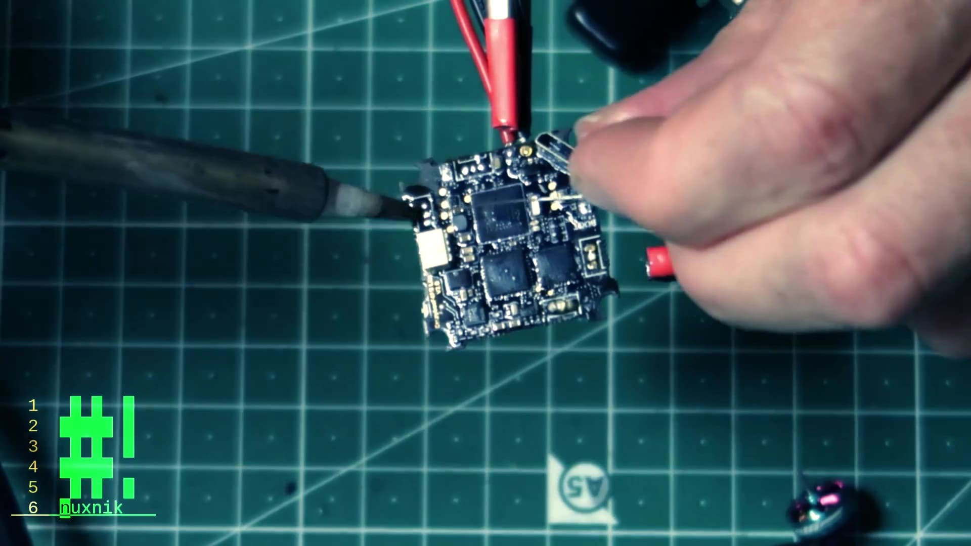
Solder the motor wires onto the flight controller

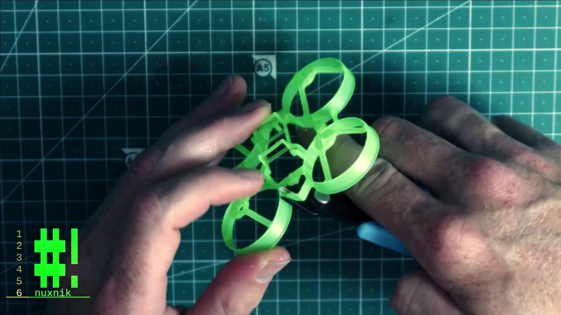
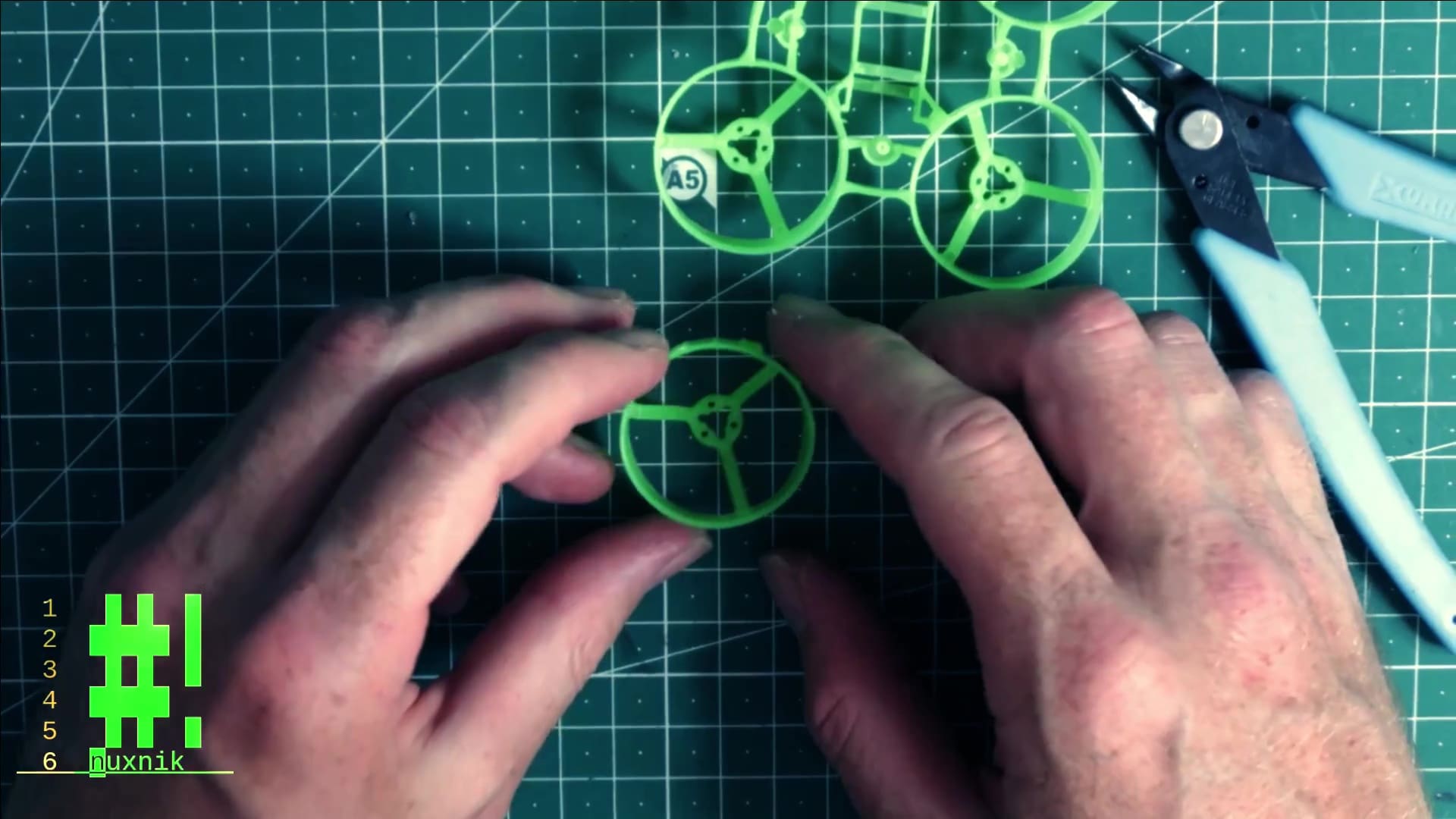
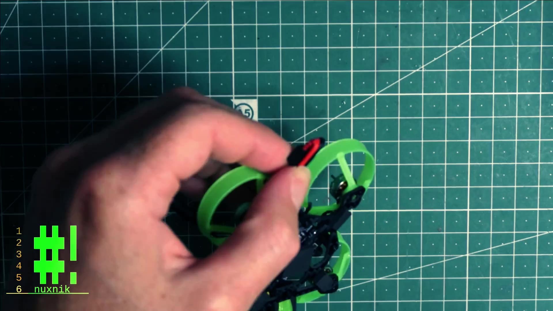
Preparing the Whoops
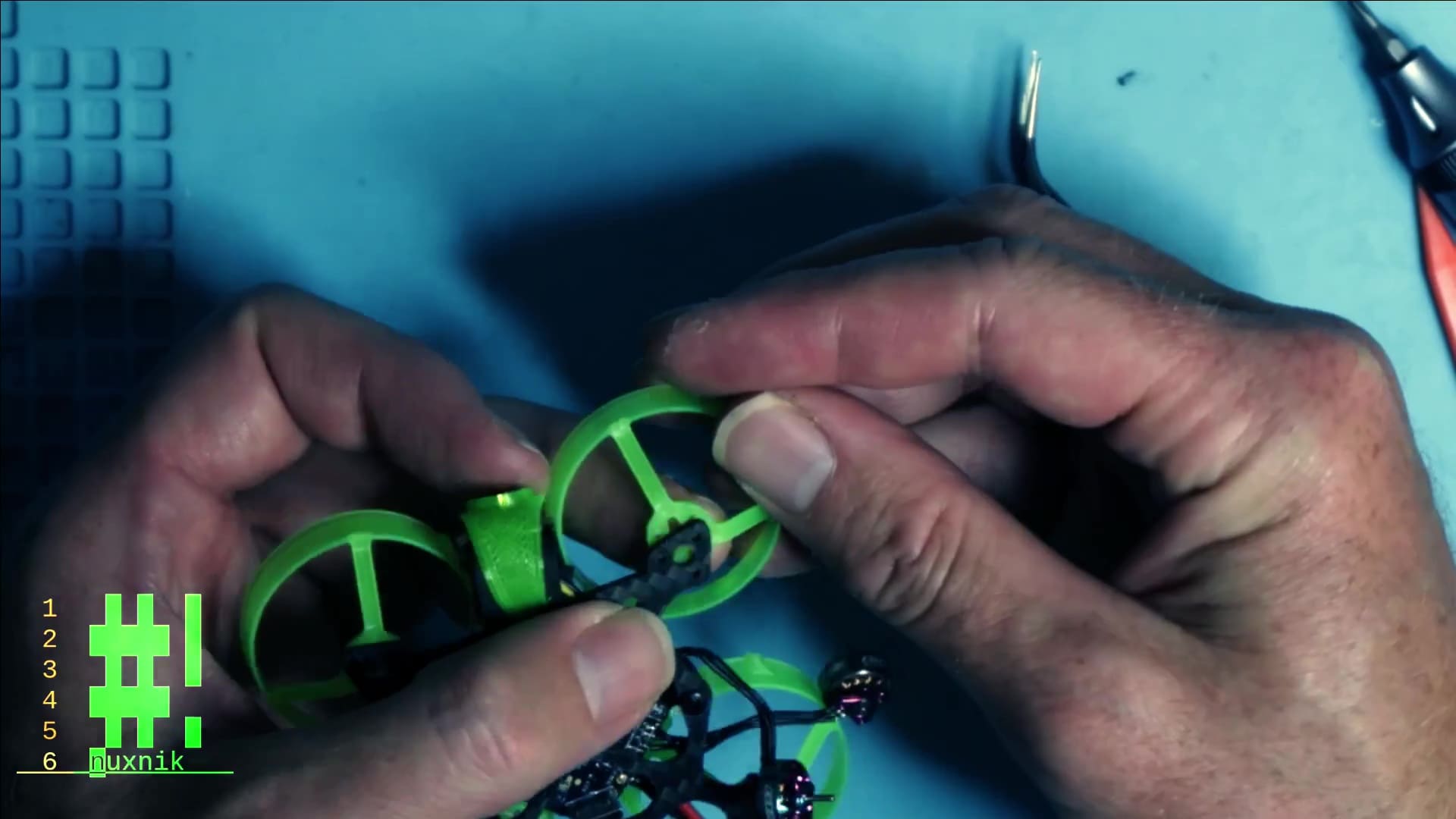
In my humble opinion, the coolest innovation of Fractal Engineering's whoop series, is that each whoop can be singly detached from the frame. This is a very useful maintenance feature. For example, if you crack a whoop, or it is beyond repair, you can easily swap it out without having to change out the entire frame.
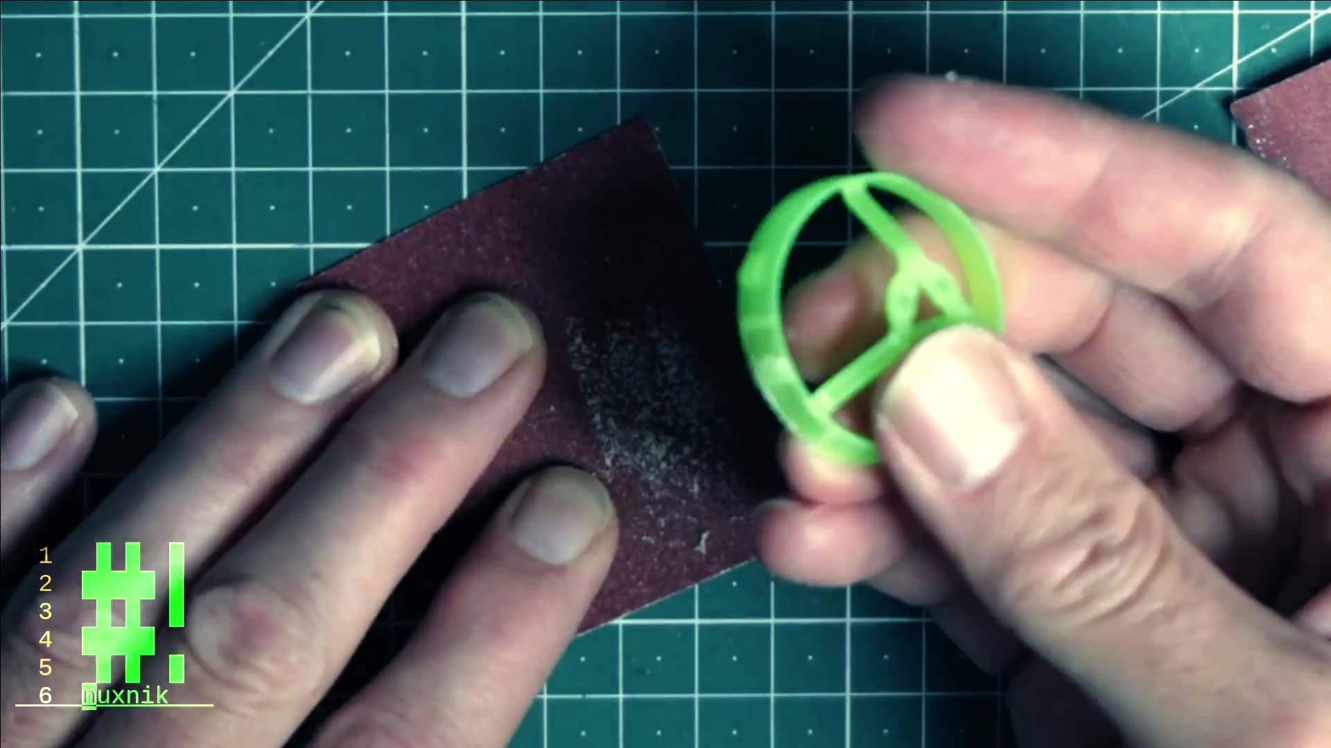
Cut out each whoop from the frame with flush cut side cutters. Try to cut as closely to the ring as possible.
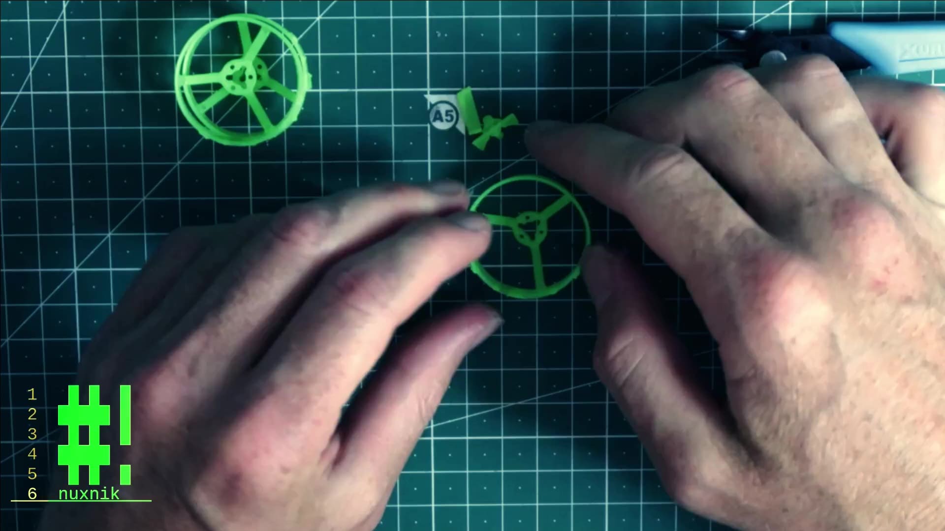
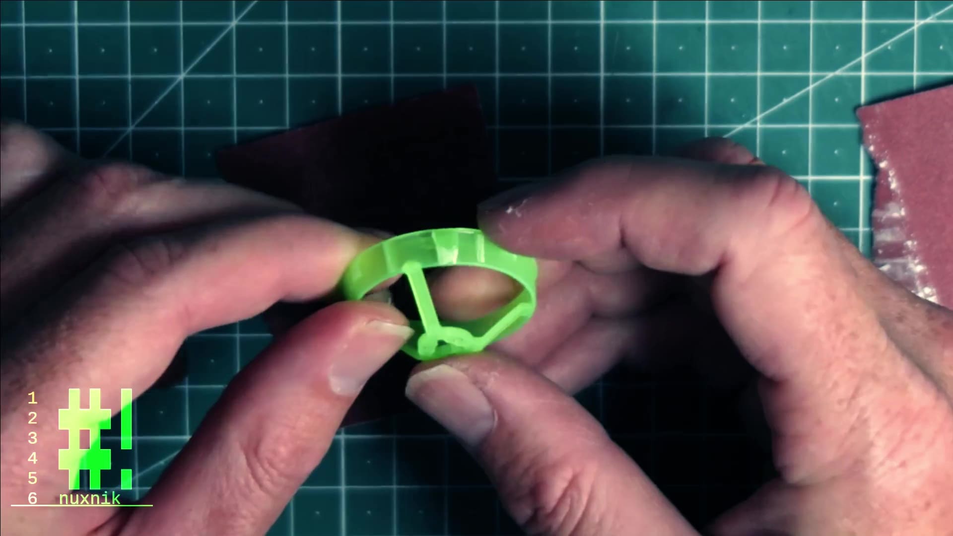
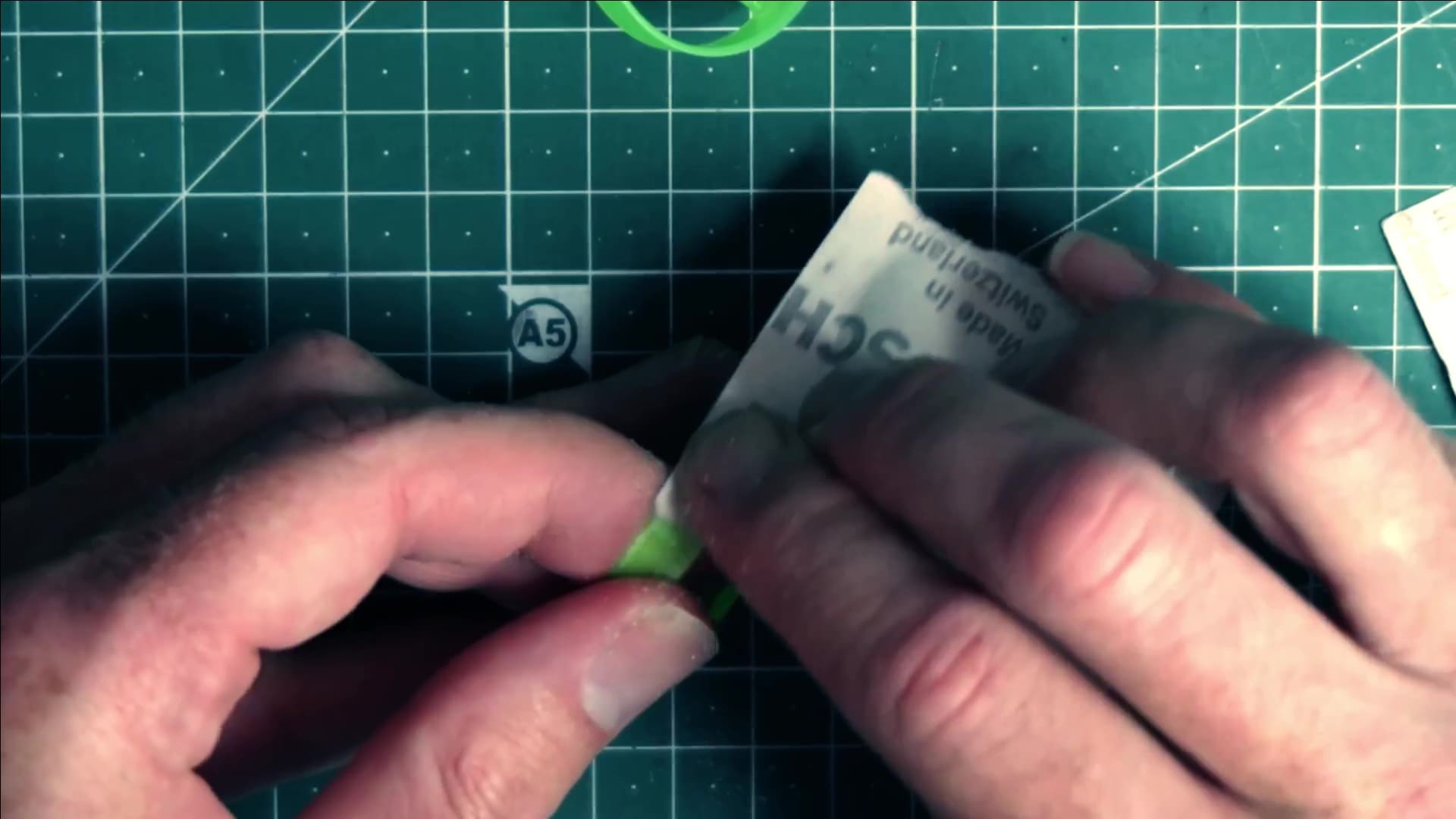
The sides of each whoop are still rough. Sand down the jagged edges with a small piece of sand paper. Firstly I used 140, then smoothed it out with 240 grit sand paper. This will remove unnecessary material. Later, it will also make it easier for the battery to slide in between the whoops.
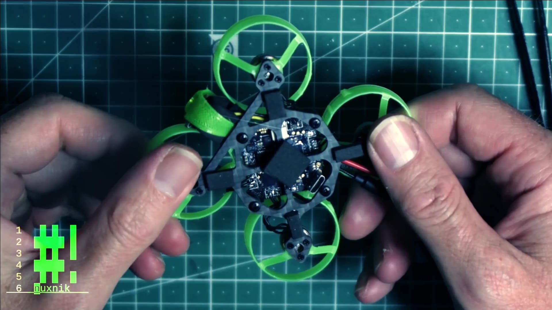
Assembly
The prep work is finished; it's assembly time!
Mount Flight Controller
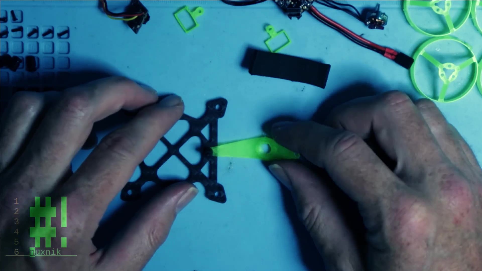
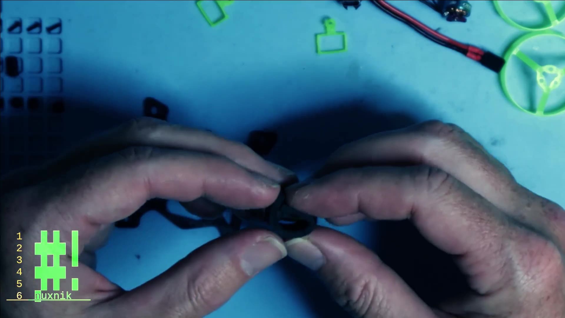
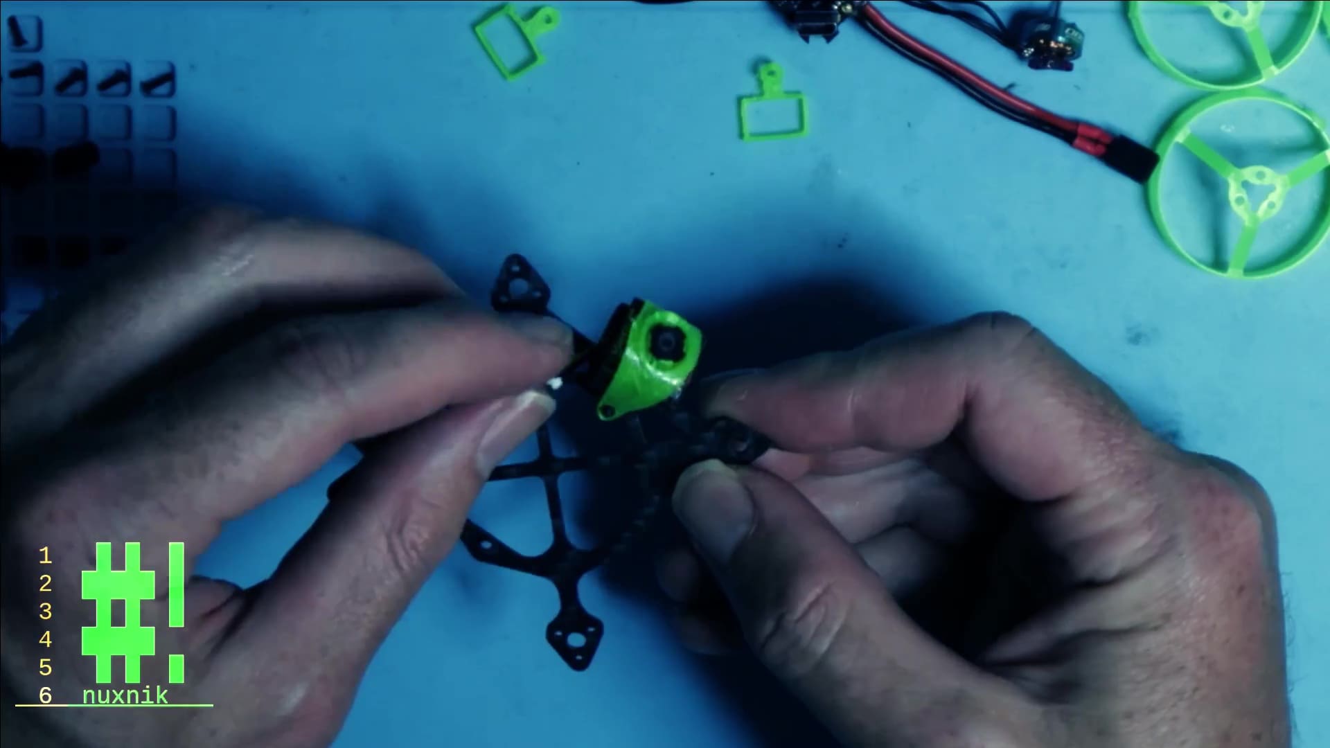
To begin, we will attach the camera mount. Insert your M2 nylon screw into the hole on the front of the frame, turn it around and place the TPU camera holder strip over the screw.
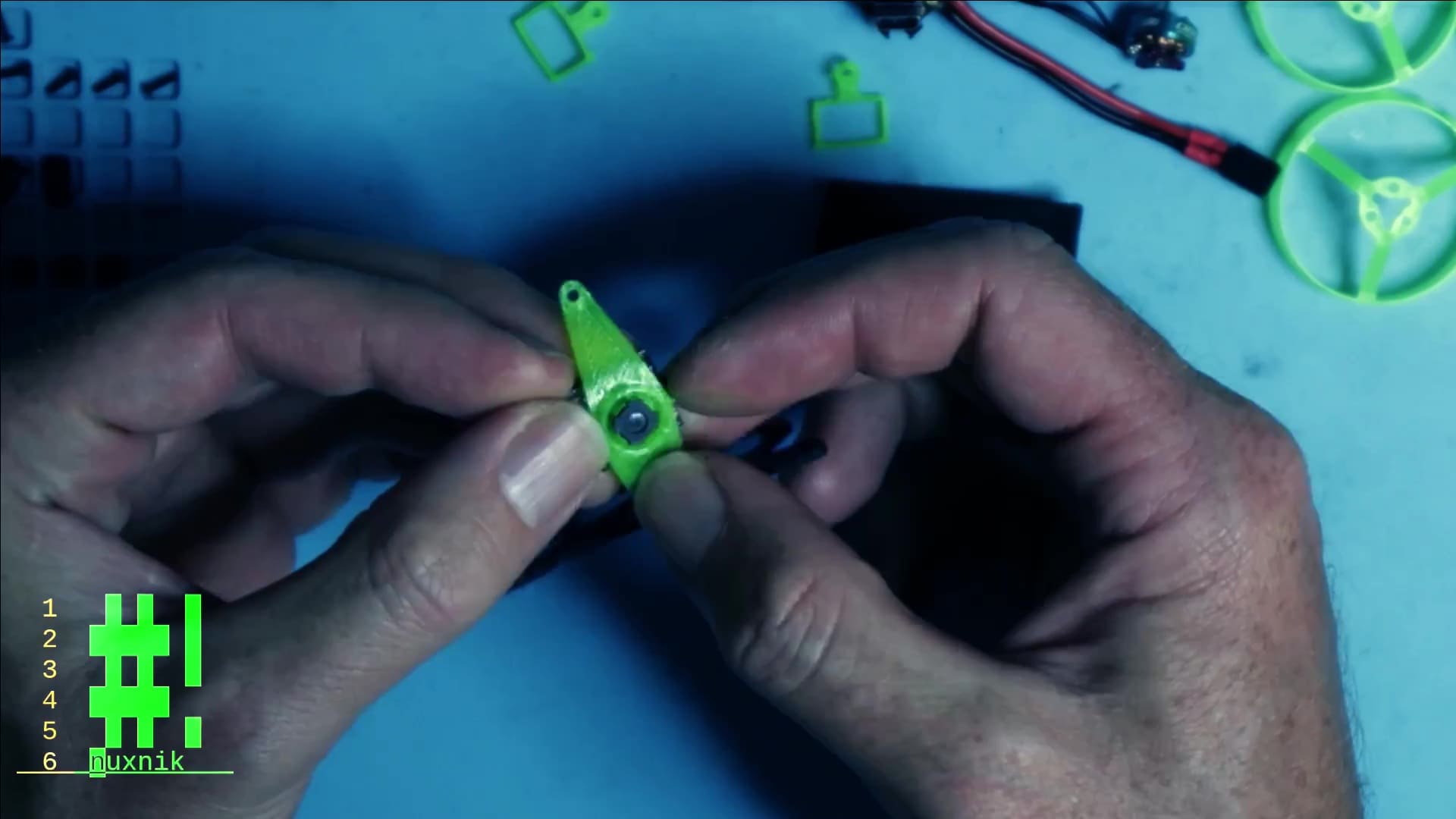
Next, place a shock absorber gummy over the screw. We can now mount the camera. Place the camera lens into the provided hole for the TPU camera holder.
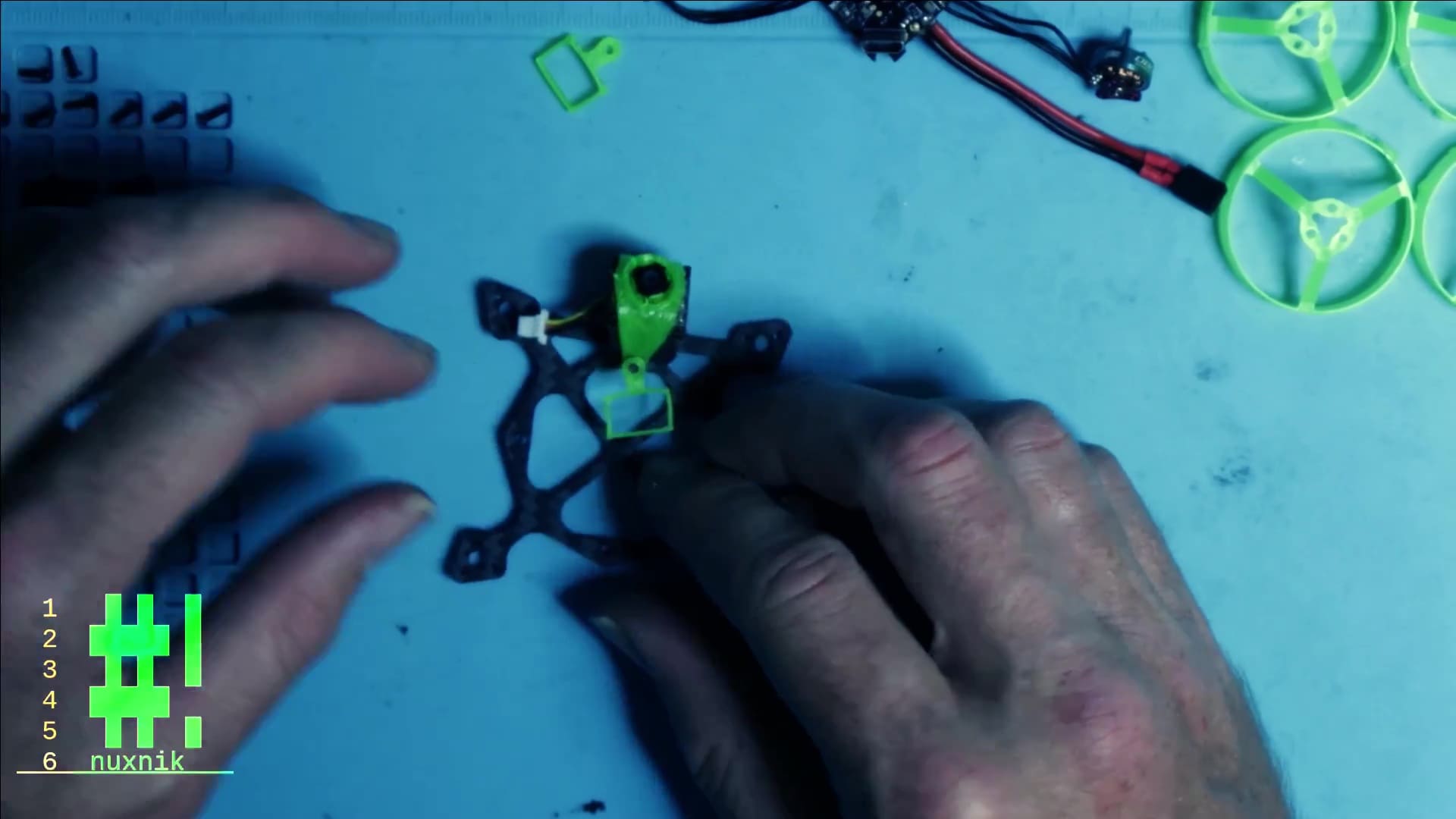
Roll a small piece of foam rubber ca. 4×1 cm into a loose cylinder and place it behind the camera. This will hold the camera into place and act as a shock absorption pillow.
While holding it in place, take the free end of the TPU camera holder and place it over the protruding nylon screw.
Place the 3D printed TPU battery holder over the nylon screw, followed by the corresponding nylon bolt.
Repeat the previous steps on the back post directly opposite, naturally excluding the steps for the camera.
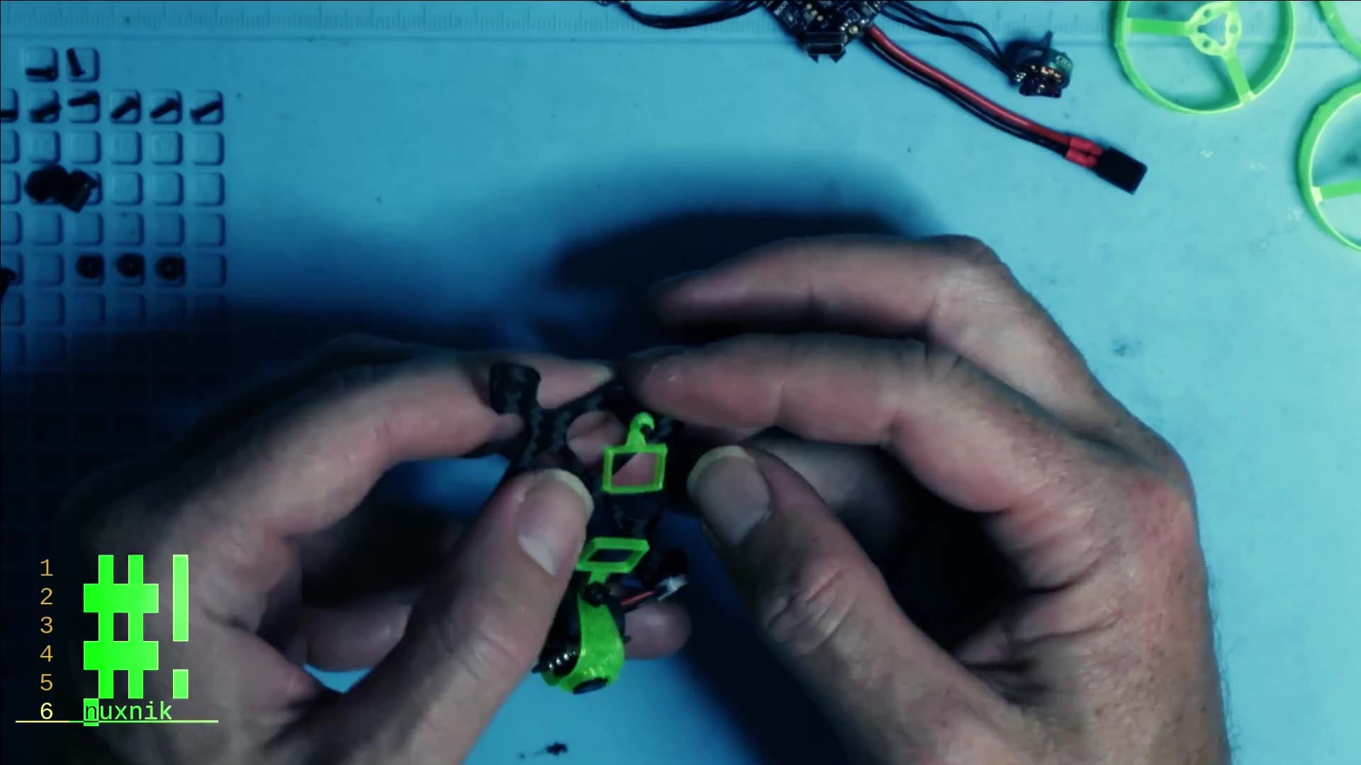
Insert the flight controller and secure both sides with two nylon bolts.
Position the remaining gummy shock absorbers on each side. Slide the nylon screws into place and secure them with two nylon bolts.

If the tips of your nylon screws extend over the bolt, take your side cutters and trim them down. Each bolt should be approximately 12 mm.
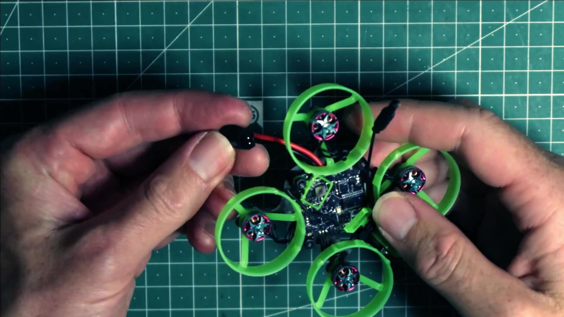
Mount Motors and Whoops
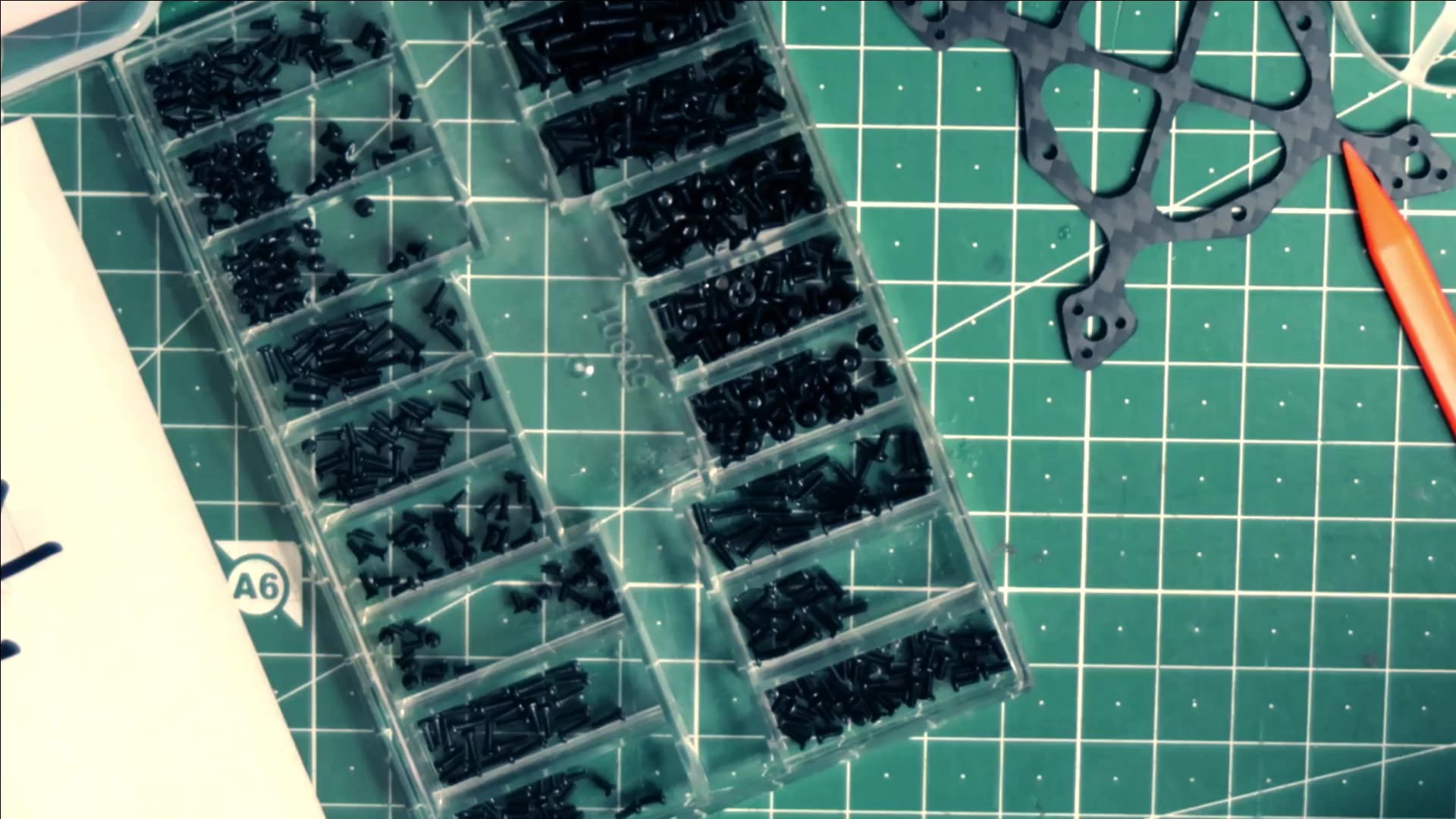
You will need 1.4×5 mm screws to attach the whoops and motors to the frame. I am using steel screws. However, you can cut down on weight by using peek or titanium screws.
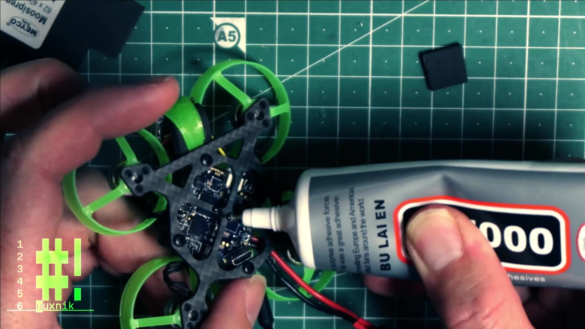
Foam skids
Nylon screws can be brittle if exposed to direct shock. On this drone, the heads of the nylon screws are exposed on the bottom of the carbon fiber plate. Let's add a few strips of foam rubber to protect them. I glued them on with B-7000
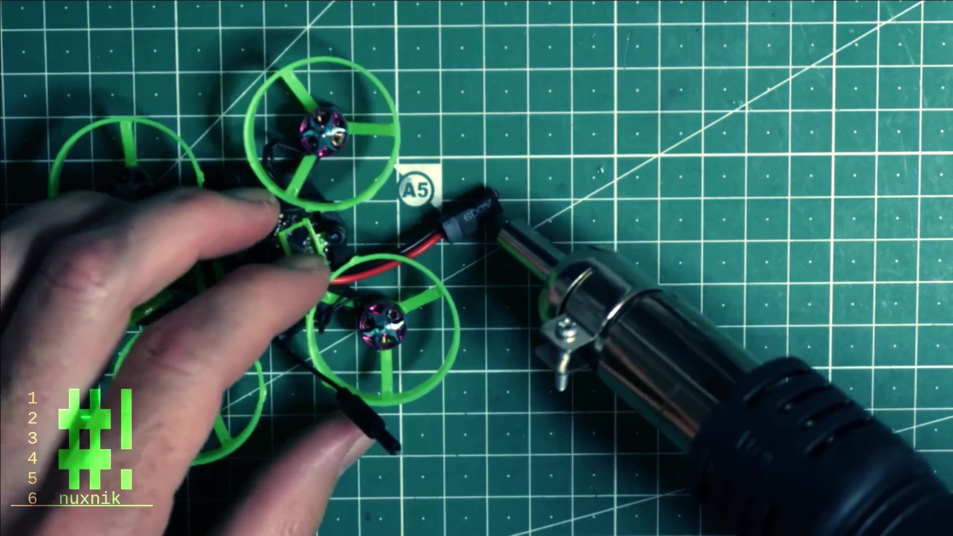
Fold A30 connector
For the final touch, let's fold the power lead back on itself. This will make it easier to plug in our batteries after mounting them on the frame.
Secure the fold with some heat shrink tubing
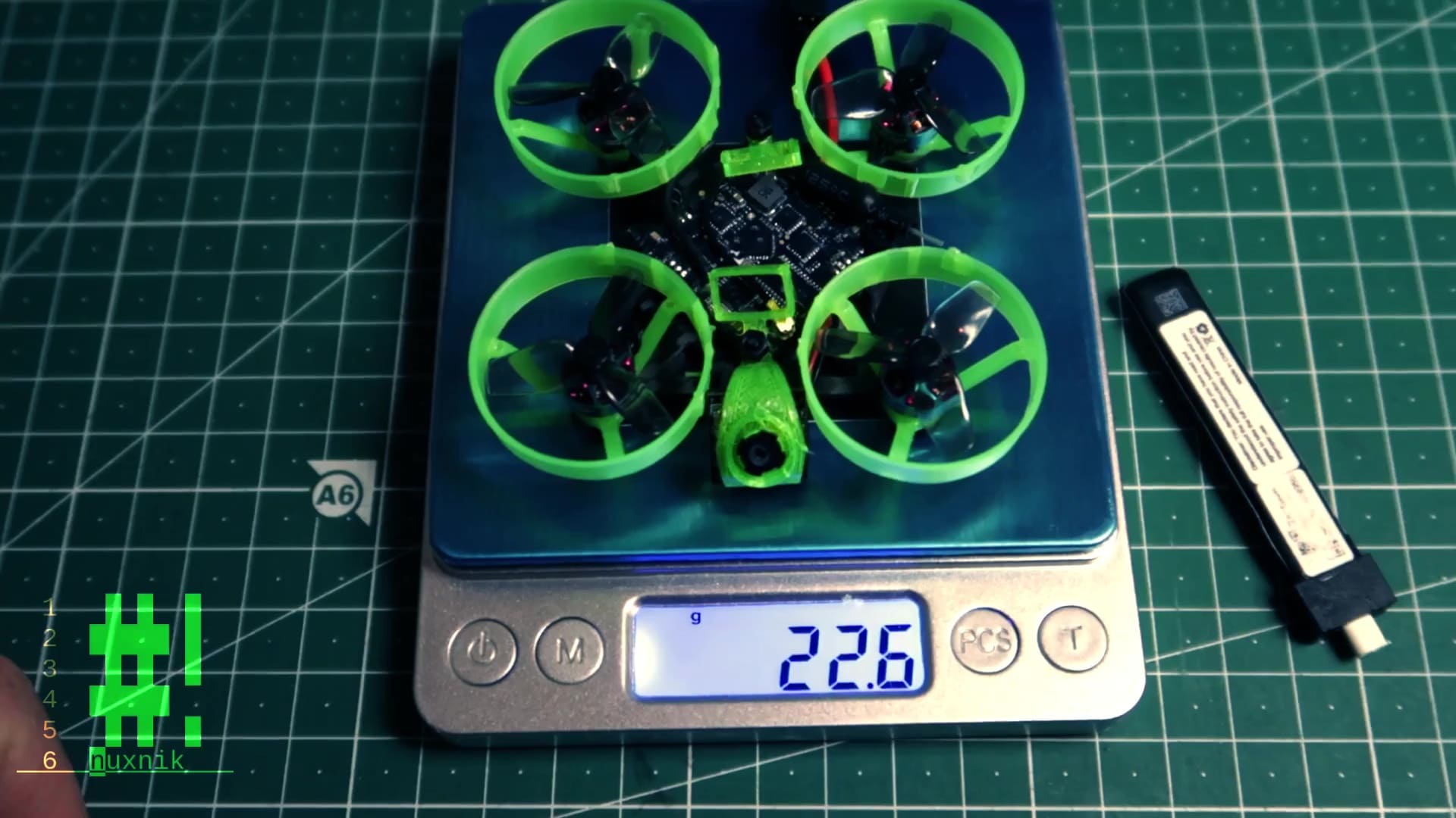
Overall Weight
Dry weight for this build is: 22.6g.
The total weight with the battery comes to: 31.1g.
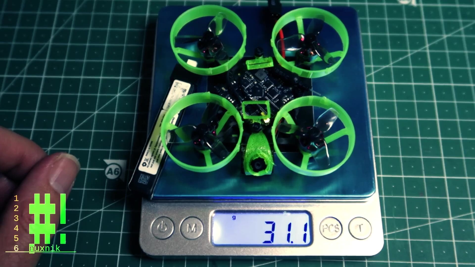
The overall weight is a bit high, however it can be improved in future iterations. For example, the UFL connector and dipole antenna add weight. Using a lighter different flight controller: Happymodel Diamond F4 would lighten the load. One could also use peek instead of steel screws for the motors. This drone is a prototype and therefore still a work in progress. In spite of the weight, this tiny whoop flies like a rocket and doesn't lack in response or power. I can easily pull out of any heavy inertia laden maneuvers and have yet to max out the throttle.
Video
As with most of my build articles, I have created a video build guide and flight test video. Please subscribe if you have a YouTube account, I would greatly appreciate it.
Final Thoughts
After participating in IGOW4 this year, I realized my most of my whoops were not up to snuff for some requirements. I was able to pull off most of the tricks, but didn't have the oomph, I needed sometimes. This got me thinking and scouring the internet for inspiration. This whoop is the product of that search. I largely solved the problem of voltage sag by switching to BT2.0/A30 connectors, but that was only half of the pie. The improved frame design, makes me less anxious about taking hard crashes. Due to the modular design of this tiny whoop, a cracked frame is a thing of the past. If a whoop bites the dust, replacing it is a simple procedure that doesn't involve taking the entire drone apart. Write your suggestions or constructive criticisms in the comments section below. Additionally, if you end up making one of these, let us know about it!