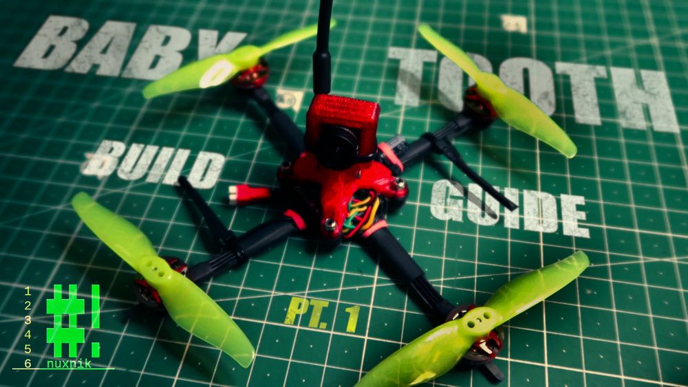
Baby Tooth Build Part 1
Synopsis
Let's build a drone! If you are not familiar with KebabFPV, check him out because today we are going to build a variant of KebabFPV's "baby tooth" FPV drone. Just what is the "baby tooth"? It is an ultralight FPV quad which typically runs on 1-2S batteries. It is small, light and very quiet when it flies. Most importantly, it offers a roller coaster flight experience similar to that of a larger, heavier quad. It belongs to a class of drones known as "toothpicks". Toothpicks usually weigh under 100g AUW[1] and typically feature tiny brushless motors, an AIO[2] flight controller, a stripped down frame and many other weight and size saving characteristics.
Required Tools
This build is going to be simple and the tools we will need are minimal. In order to complete this build, you will need the following tools:
- Soldering iron and soldering accesories
- Tweezers
- Hex drivers
- Scissors
- Heat gun or lighter
BOM
As mentioned above, this is a variant of the original baby tooth. Below I have listed the vendors I ordered my components from:
| Qty | Component | Price |
|---|---|---|
| 1 | Eachine Nano VTX | 20.00€ |
| 1 | Carbon Fiber Frame | 12.00€ |
| 4 | RCINPower GTS V2 1202.5 6000KV | 50.00€ |
| 1 | JHEMUC Play F4 FC | 40.00€ |
| 1 | RunCam Nano 2 | 20.00€ |
| 4 | Gemfan 3018 Propellers | 8.00€ |
| 1 | XM Plus Receiver | 20.00€ |
| Total: | 170.00€ |
The prices displayed here will vary over time. Needless to say, due to the chip supply chain being disrupted by the virus I will not name, the prices have gone up significantly over the past year.
Some of you might notice I am using some of the same components as in my #NanoLongRange Build Guide. I bought many of these components at the same time, that is why they are similar. Besides, it will keep the builds uniform and easy to follow.
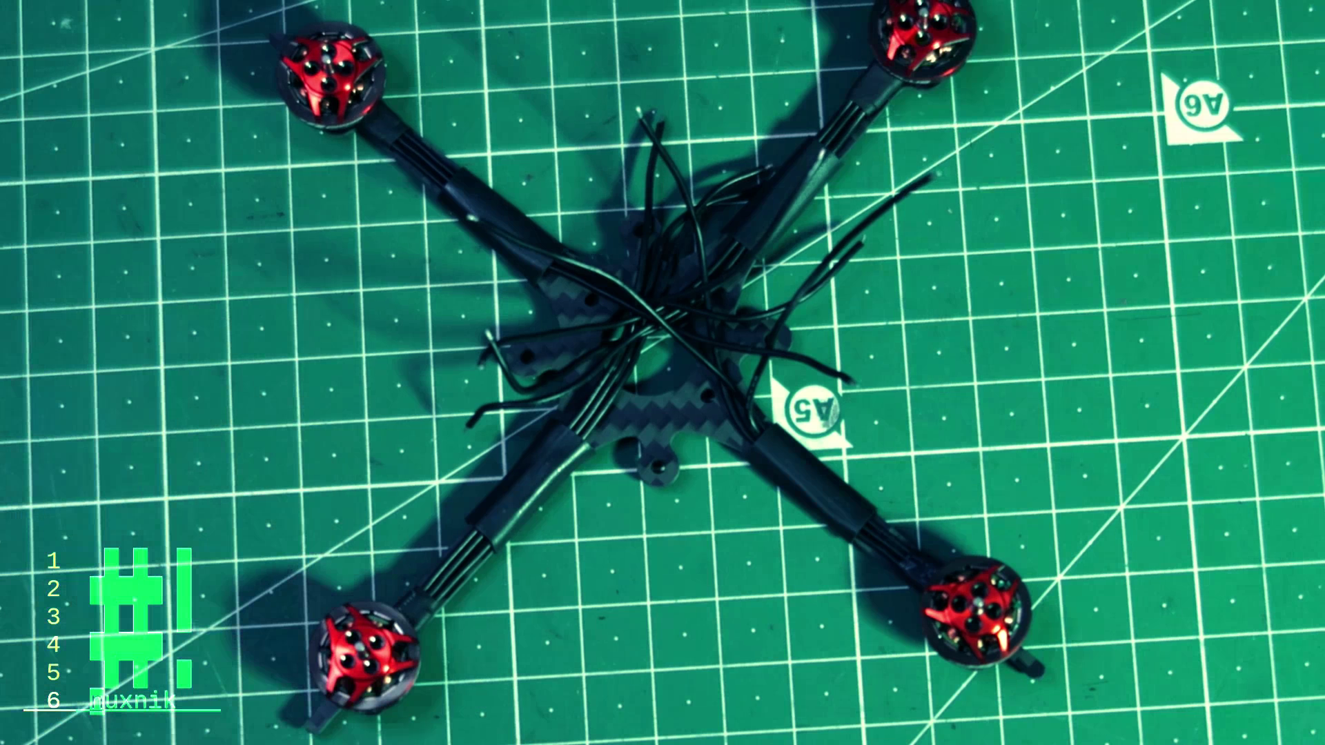
Frame Preparation
Before getting down to the nitty-gritty of the electronics, let's prepare the frame and get it ready to mount the other components.
Mounting the Motors
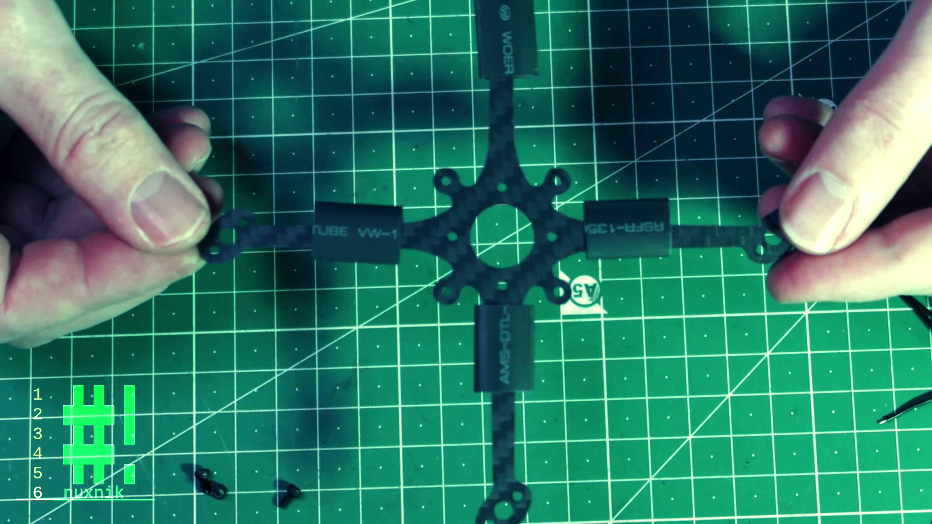
For the first step, we need four pieces of 15mm heat shrink tubing cut down to 20mm strips.
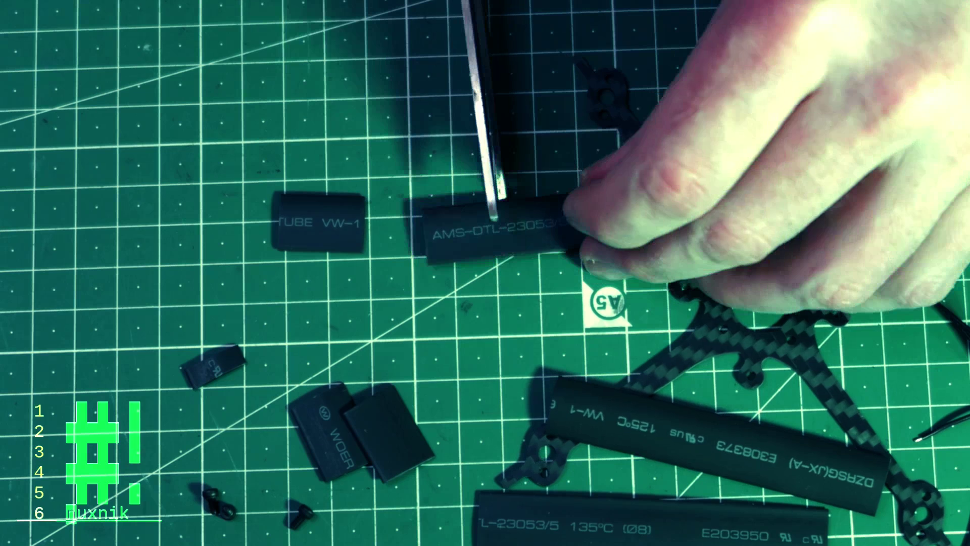
After cutting the strips, insert each piece over each of the four arms. They should look like small sleeves.
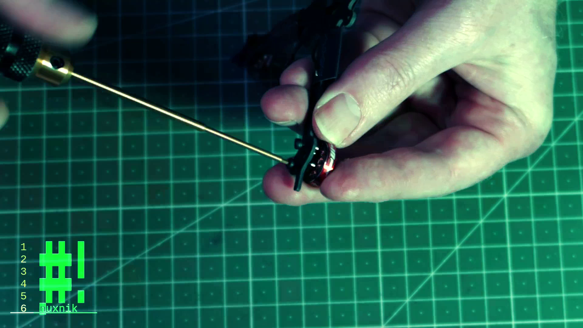
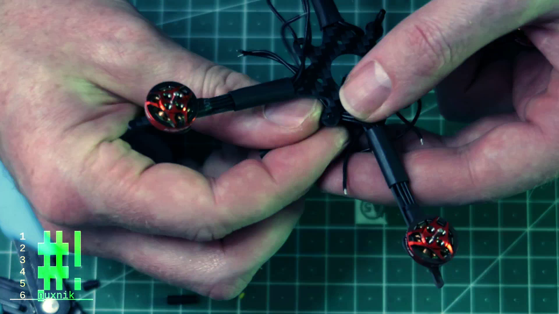
Slide the motor wire underneath the heat shrik tubing and screw the motor onto the arm. As an optional step, you can additionally add a small drop of Loctite to the screw threads to keep them from coming loose. This can happen over time as the vibrations slowly turn the screws - Loctite stops this.
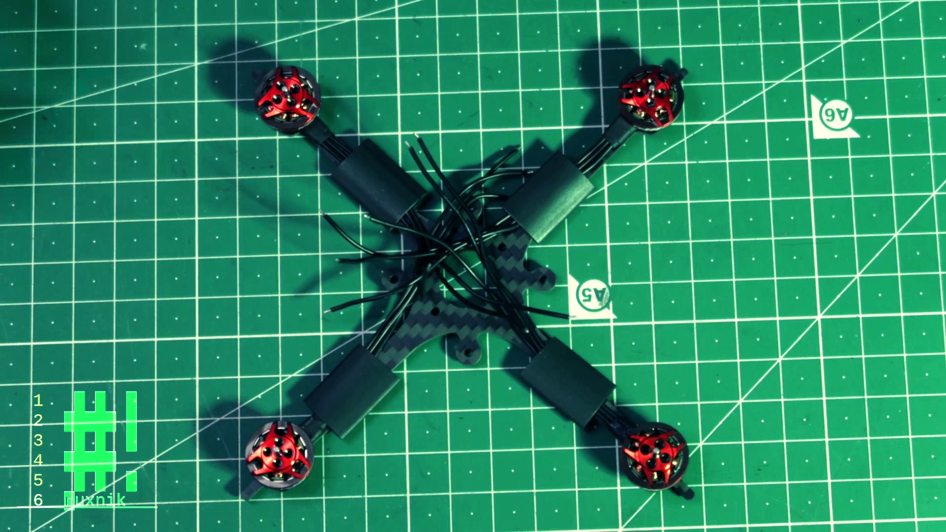
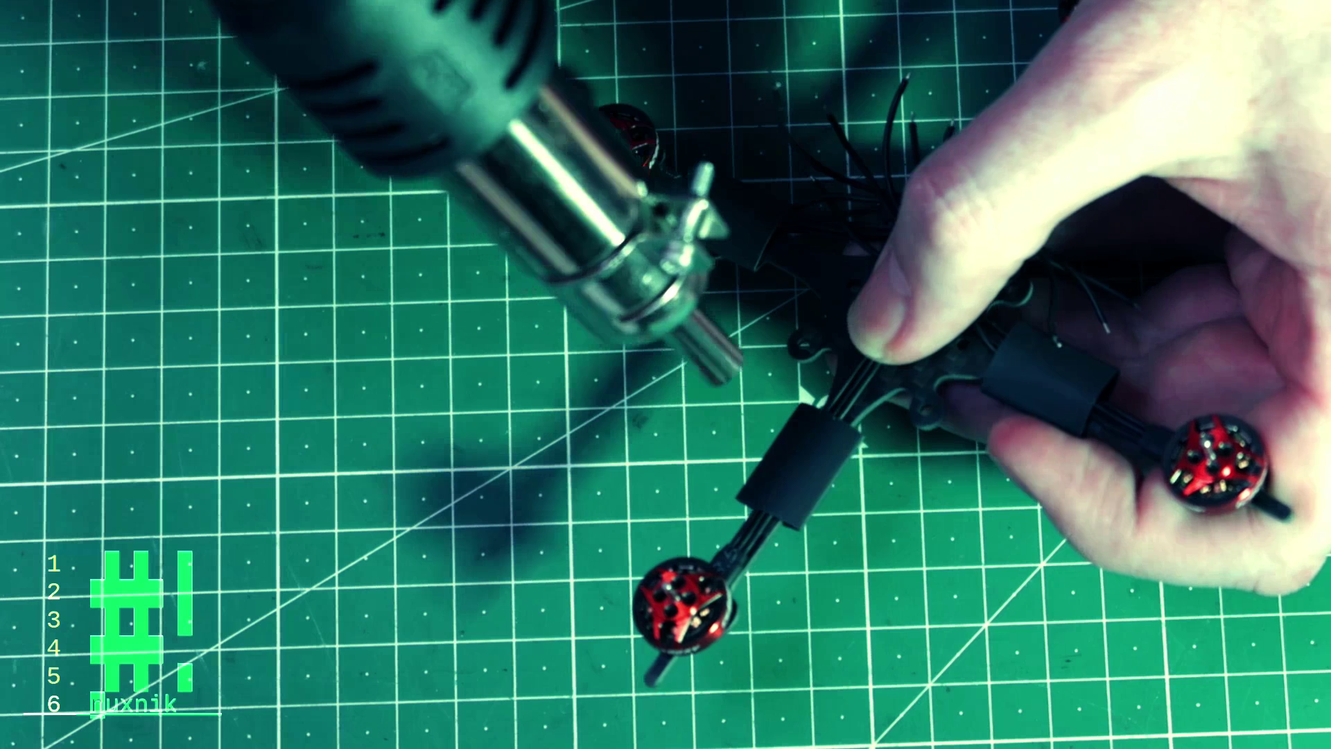
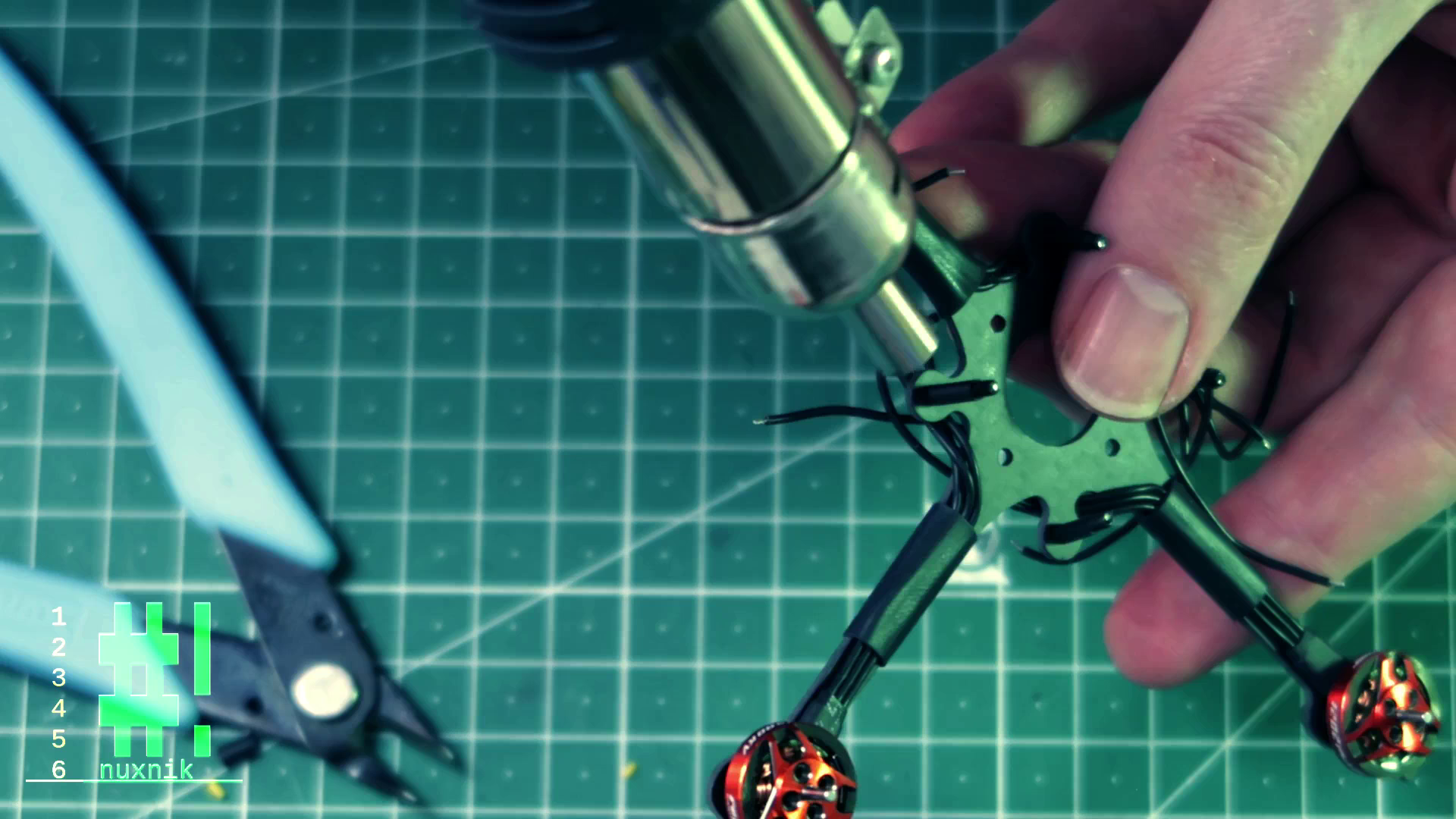
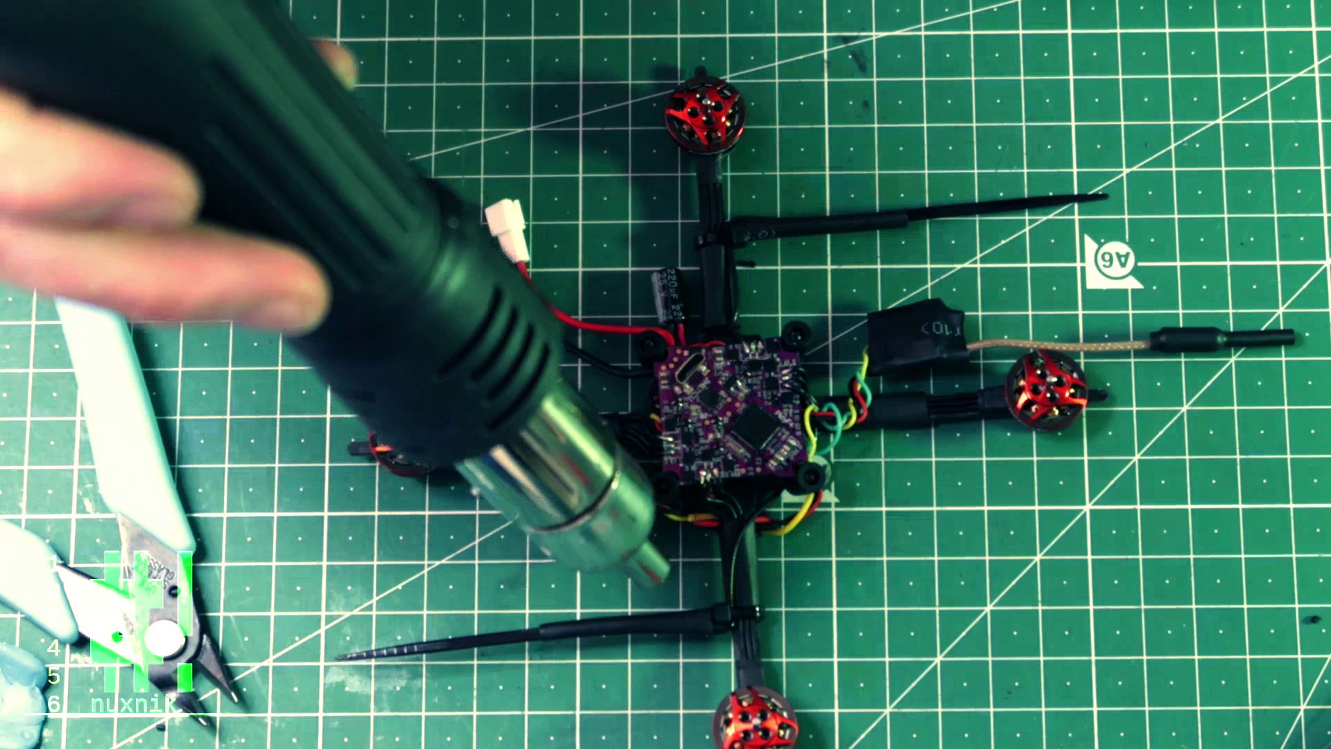
To finalize the motor mounting process, get a heat gun or a lighter and shrink the tubing around the arms. These heat shrink sleeves will protect the motor wires and will keep the build nice and neat. Before applying heat, make sure the motor wires are not crossed underneath the heat shrik tubing.
Mounting Screws
We can now prepare the mounting screws which will hold the canopy and electronics. After inserting the mounting screws throught the bottom of the frame, we will add 50mm of heat shrink tubing over each of the screws. This will keep the screws from falling out later when we mount the flight controller. The frame screws are M2 size and my rubber grommets are M3. That is why I am adding the heat shrink, to make them fit tighter. This is step is optional, so feel free to skip.
After adding the heat shrink, we'll blast it with the heat gun to make it hold.
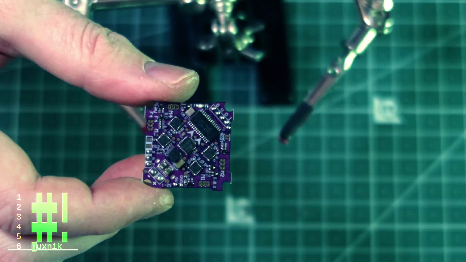
Flight Controller Preparation
Pre-tinning the solder pads of the flight controller will make our lives easier when mounting the external modules. With that said, heat up your soldering iron and get your solderflux and tweezers. To prepare, we will be adding solder blobs to the following pads.
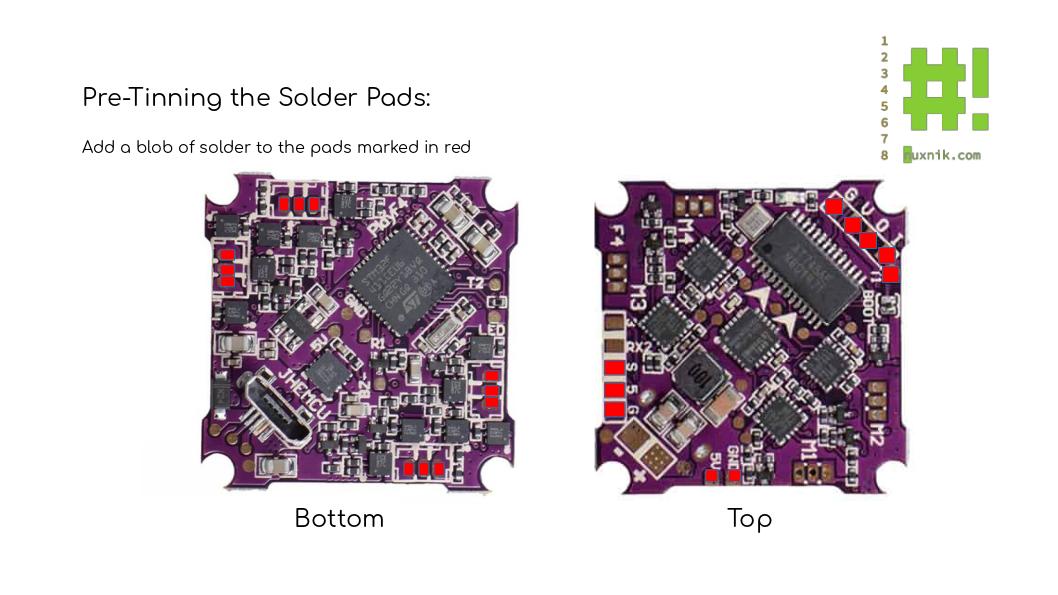
TIP: Before soldering add a little flux to each pad.
Turn the board over and pre-tin the motor pads on the bottom side:
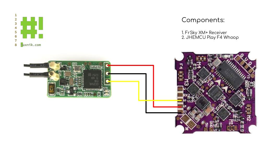
Wiring up the Receiver
Let's focus on the receiver now that the flight controller is ready to go. For this build, I am using a FrSky XM+ receiver. The wiring diagram shown above is specific to this type of "SBUS" receiver. Wiring can be different depending on the receiver you use, so make sure to do your homework and connect the correct pads.
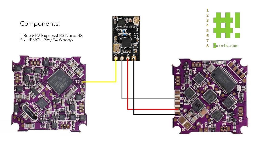
ExpressLRS
For those of you who prefer a more modern receiver, here is a wiring diagram for an ExpressLRS nano receiver. This receiver has almost the same form factor as the XM+. This receiver will require an extra UART pad. Software configuration options will be discussed in part 2 of this build.
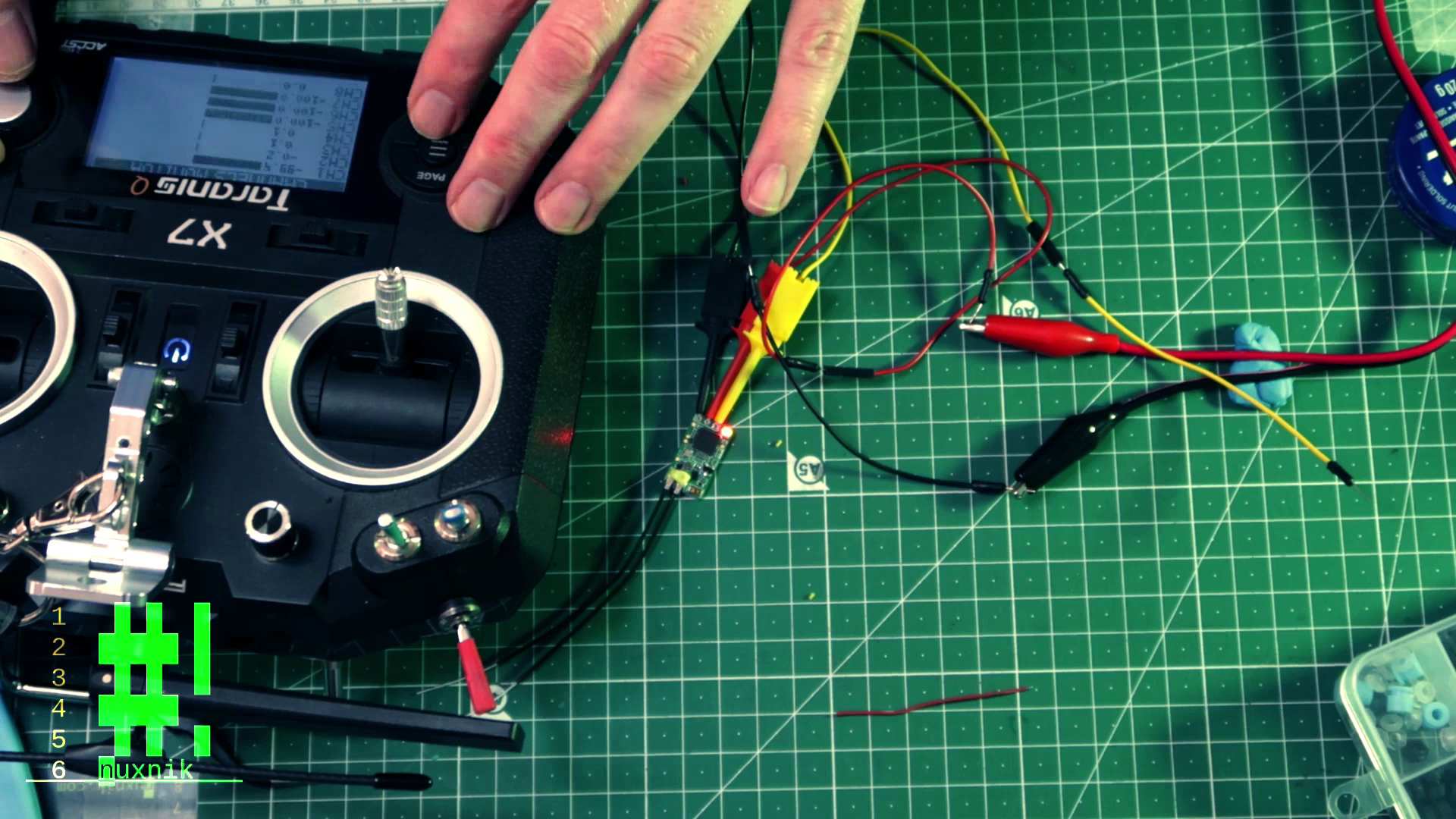
Binding the Recevier
Firstly, let's prepare the receiver (RX). Before wiring it up, we'll bind it to our transmitter. In order to do this, I am powering the recevier from my bench power supply with 5V. If you don't have a power supply, you can skip this step and do it later when you power the flight controller with a battery. Important: make sure to do this before assembling the rest of the drone and tucking the receiver away under the flight controller. It can be a drag if you have to take everything apart again later because you forgot to got through the bind process.
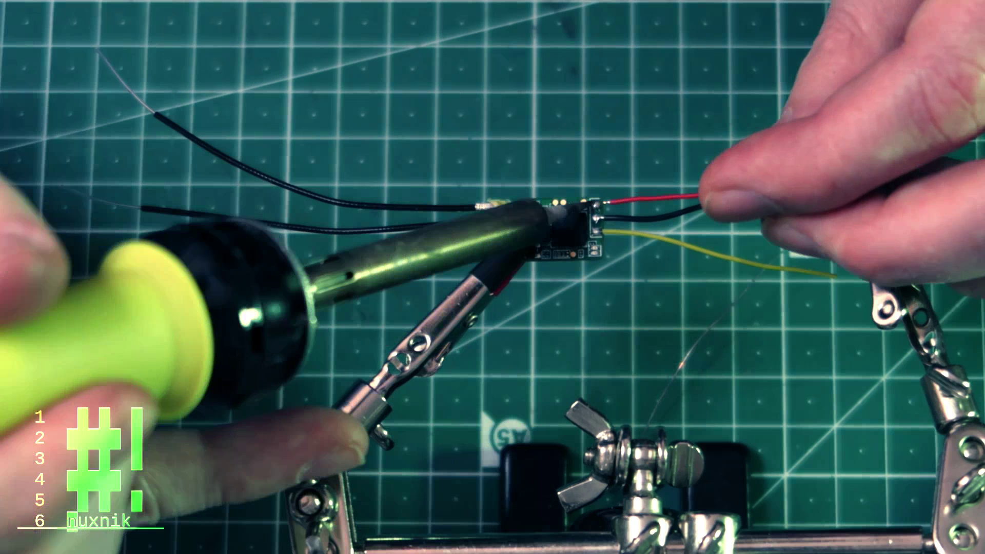
Adding the Leads
If you are using an XM+ receiver, you will want to connect it to the SBUS pad of the flight controller. Each wire is appoximately 40mm long for each lead. You should try to keep all your leads as short as possible. In this case, you can probably get away with 30mm or less. This can cut down on the overall weight and improve the flight performance. Make sure to twist the leads together.
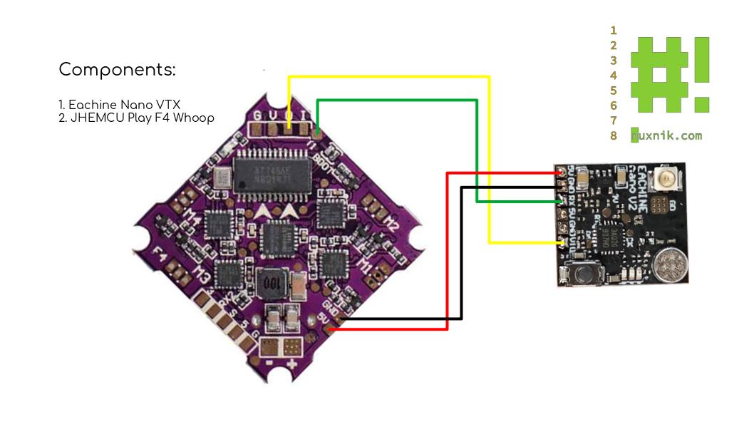
Wiring up the VTX
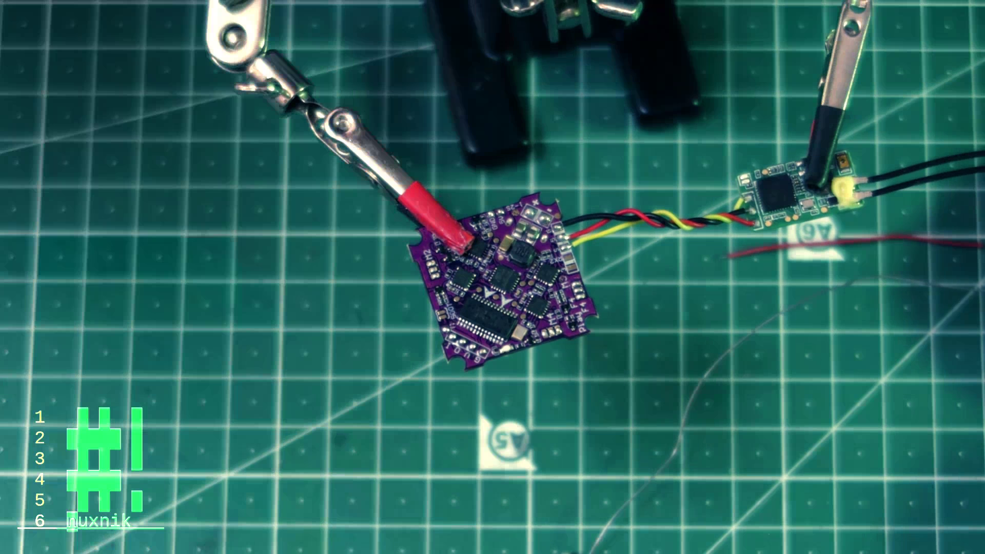
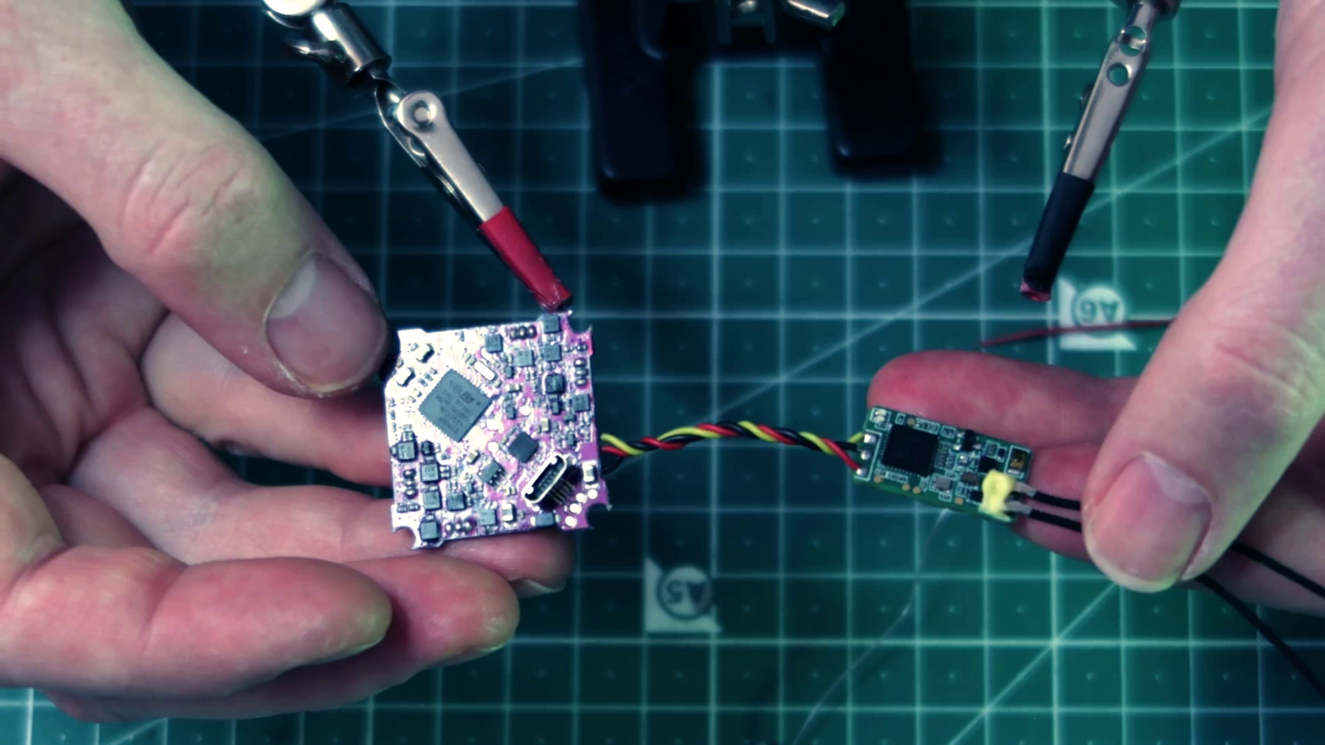
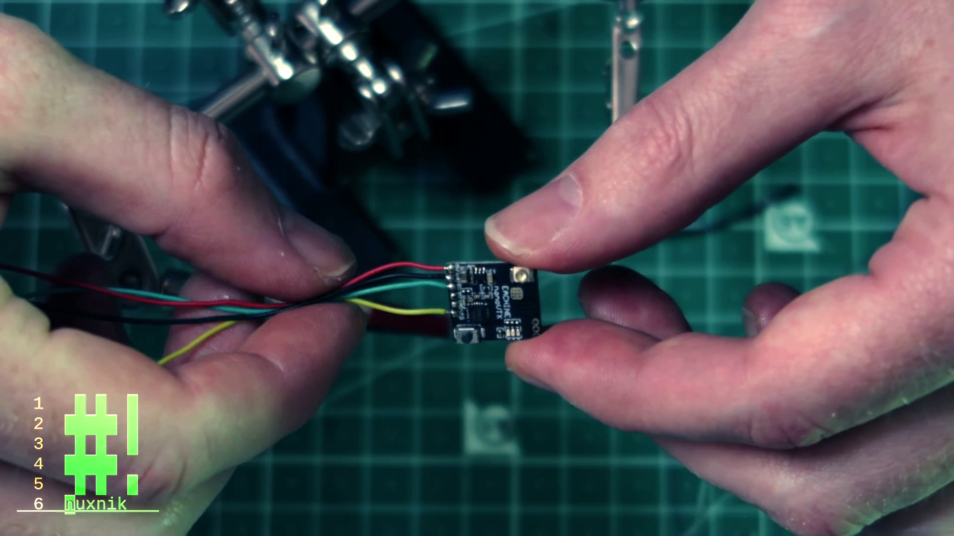
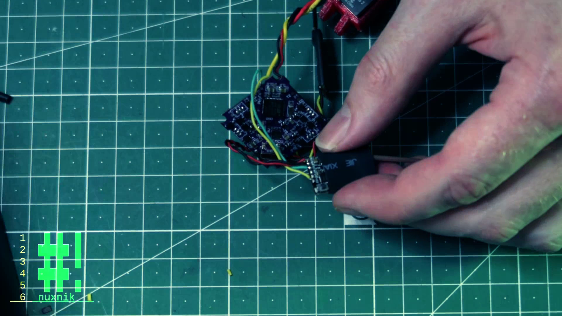
Now that the receiver module is soldered and ready to go, let's focus on the VTX. We will be using the Eachine nano VTX V1.
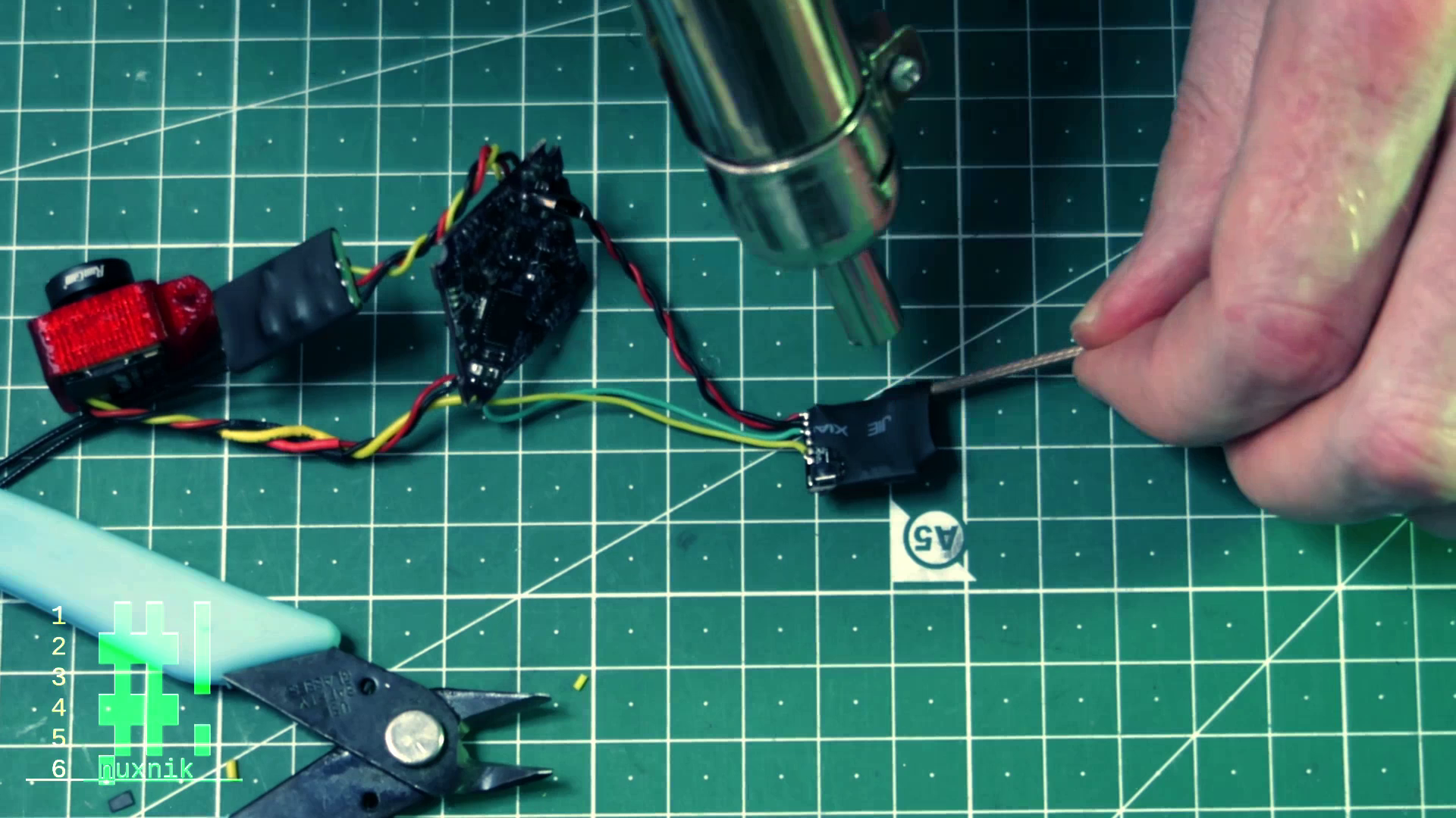
Before soldering the VTX to the flight controller, let's remove the additional leads that come presoldered onto the Eachine board.
Next we will pre-tin the leads and solder them directly to the flight controller.
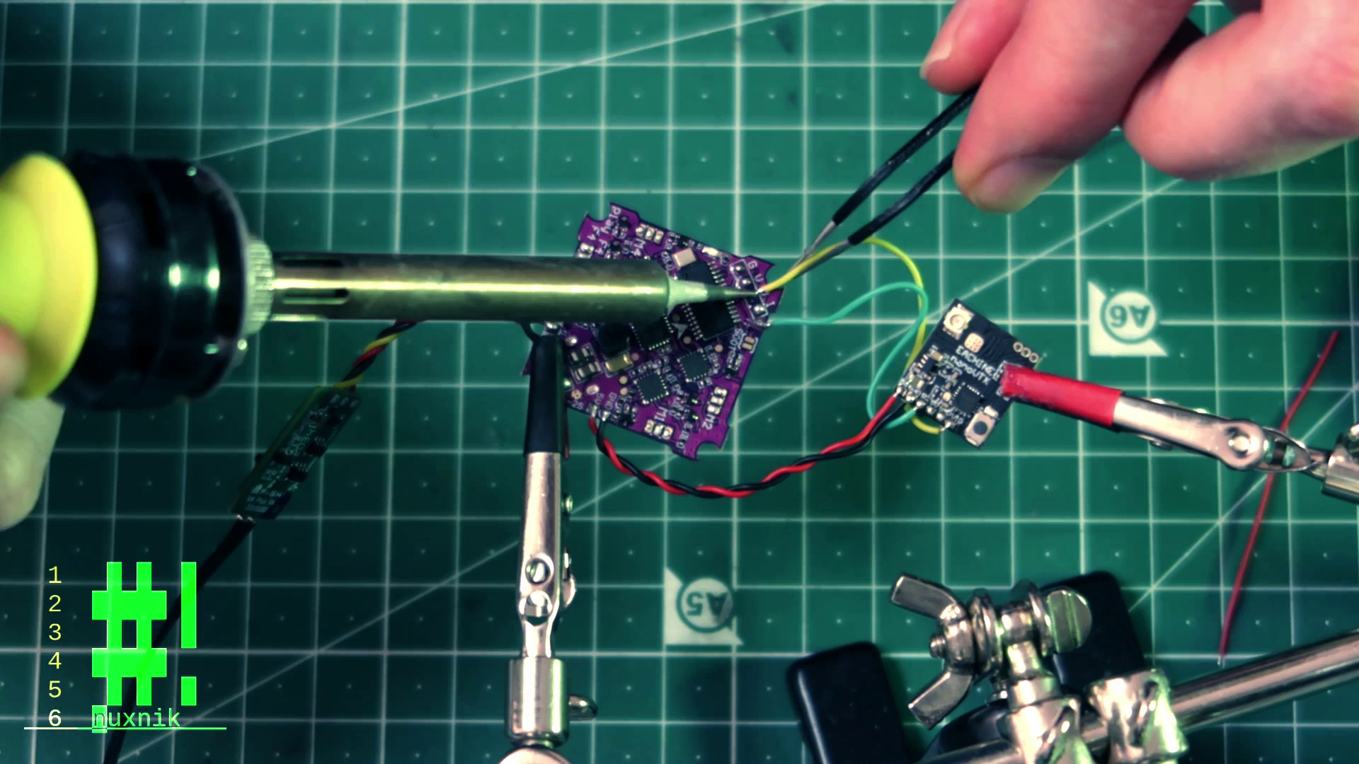
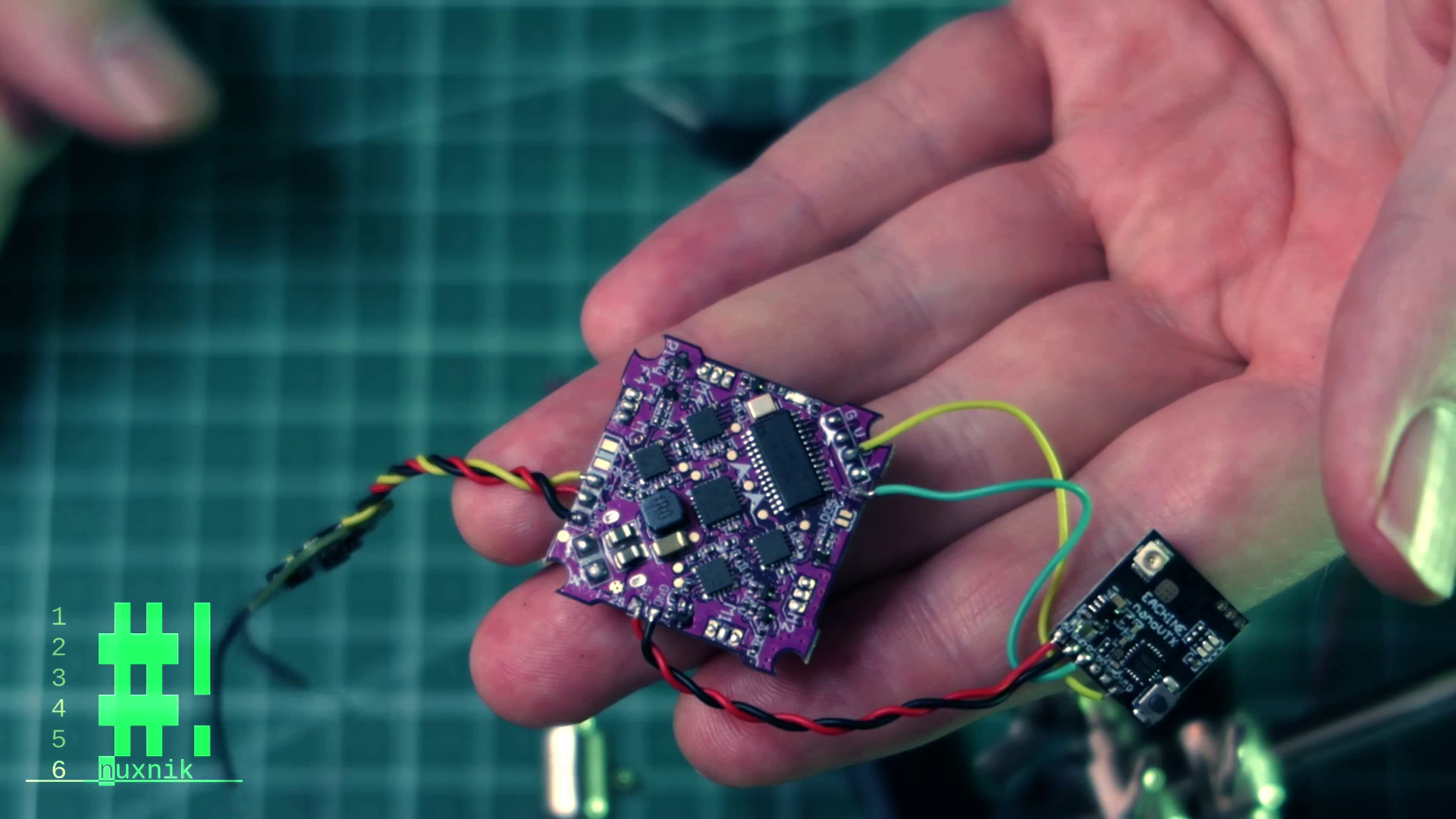
Wiring up the Camera
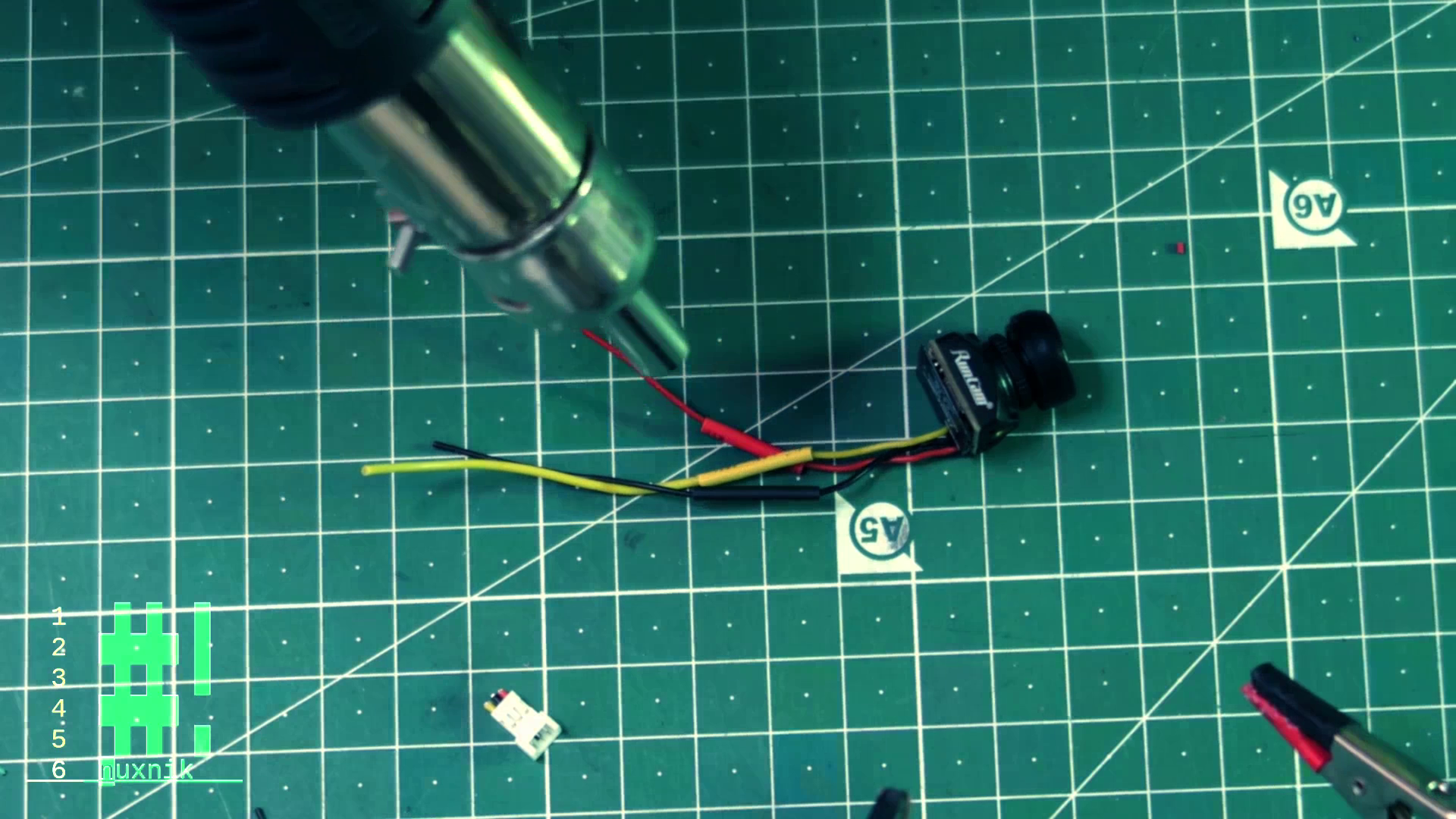
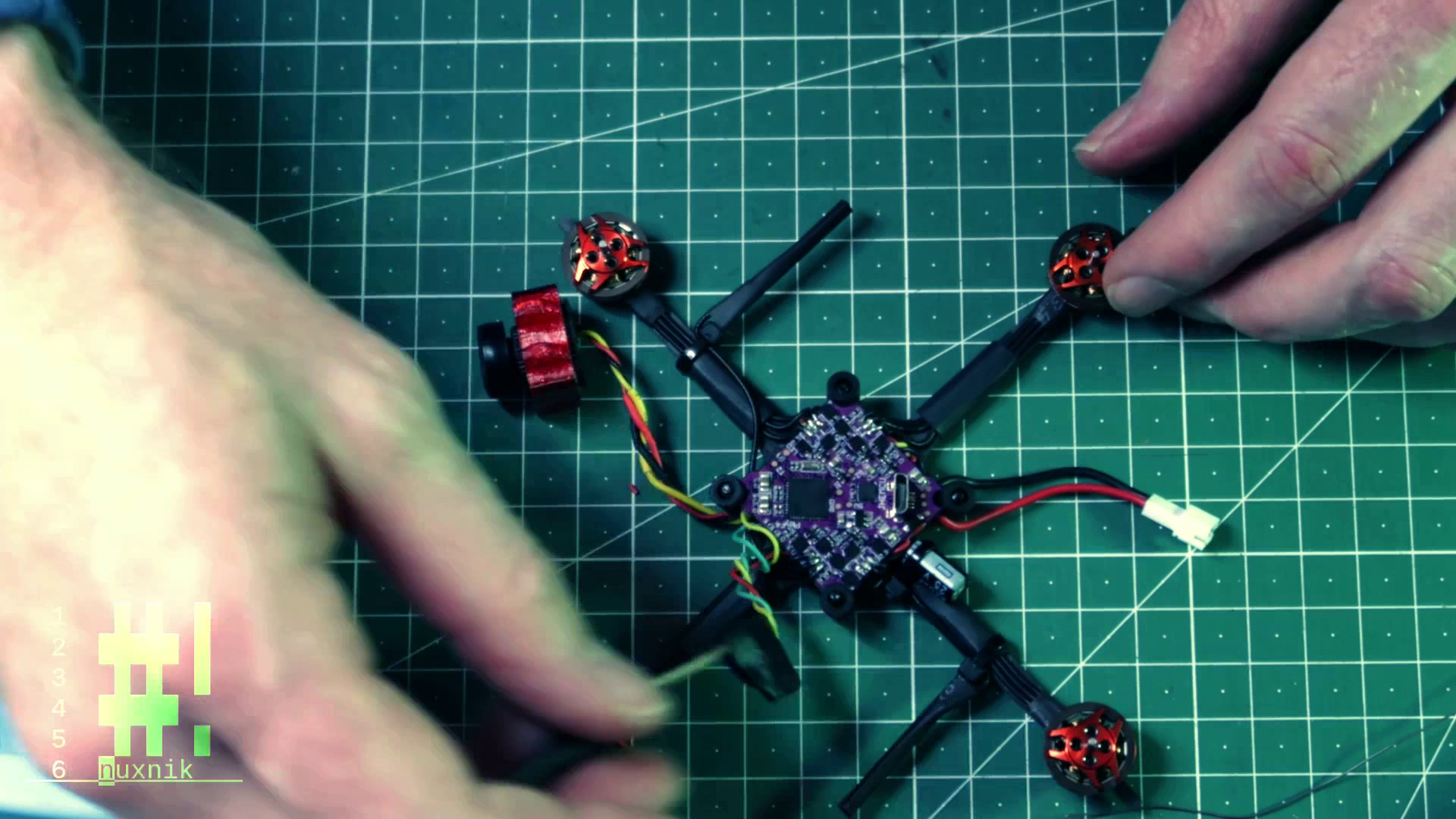
The final module we will be connecting to the flight controller is the camera. For my build, I am using the Runcam nano 2.
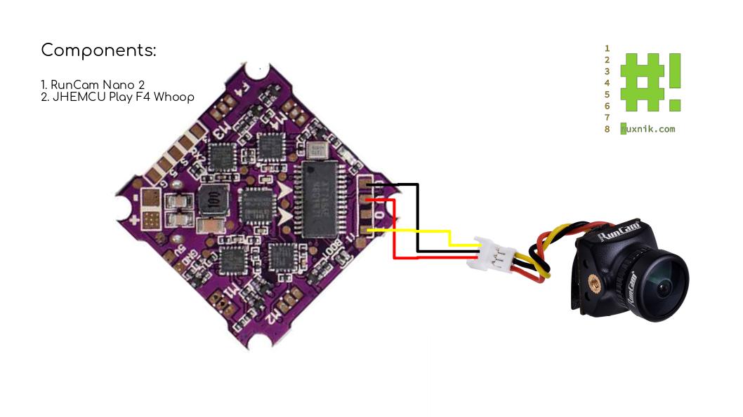
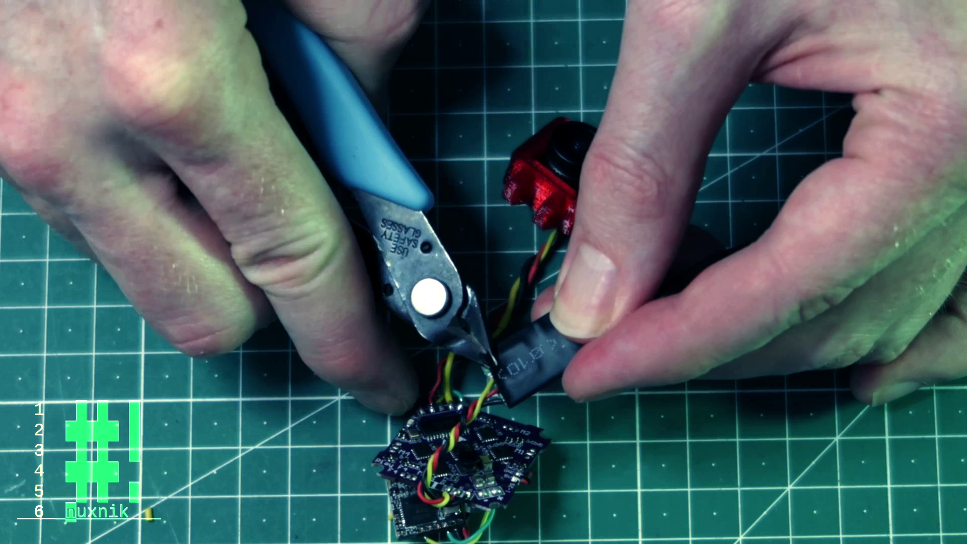
The leads from the runcam nano 2 are too short. Let's snip off the connector plug and extend the wires by 50mm.
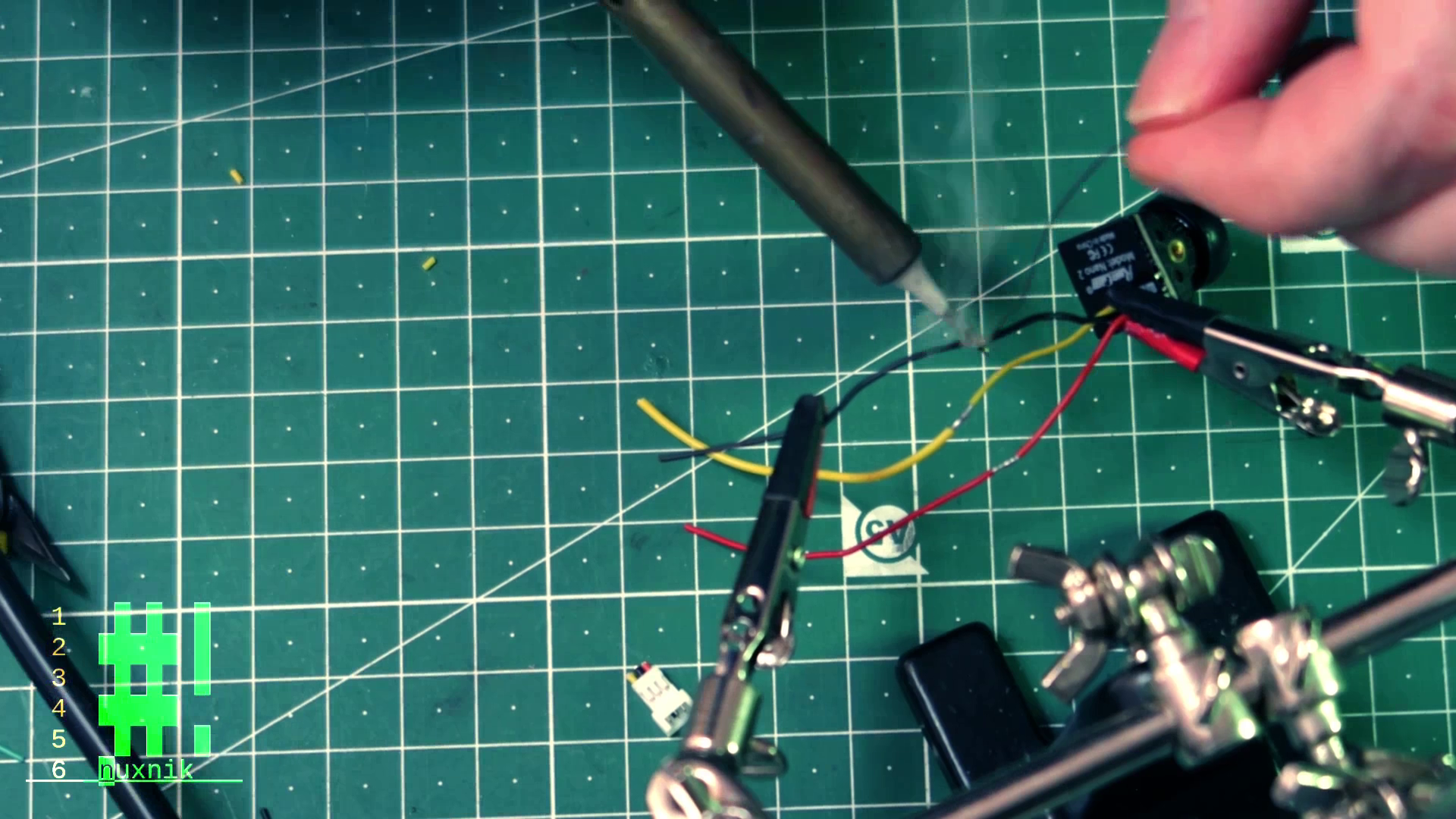
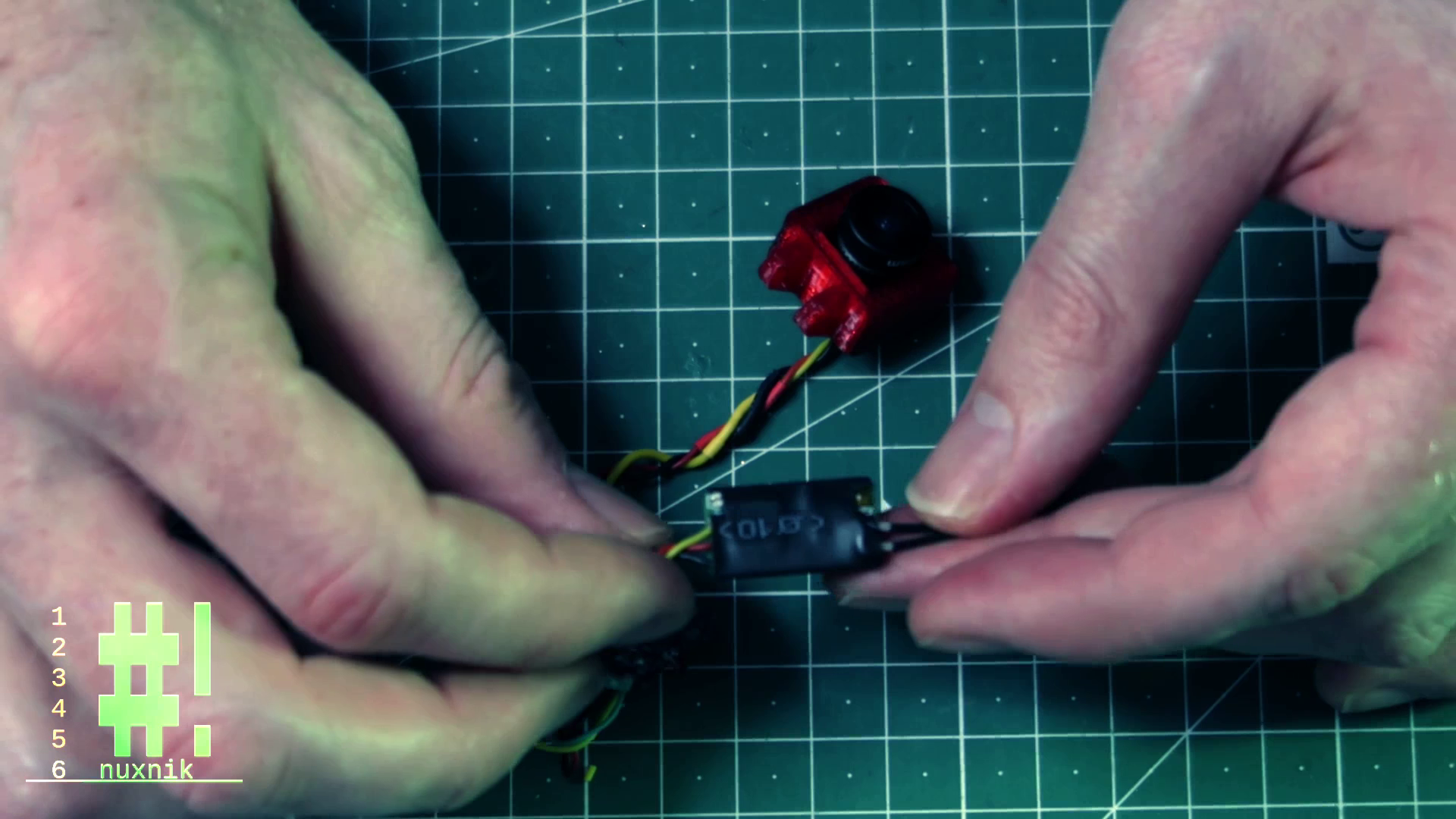
After extending the wires, let's add some color appropriate heat shrik tubing to cover the exposed solder joints.
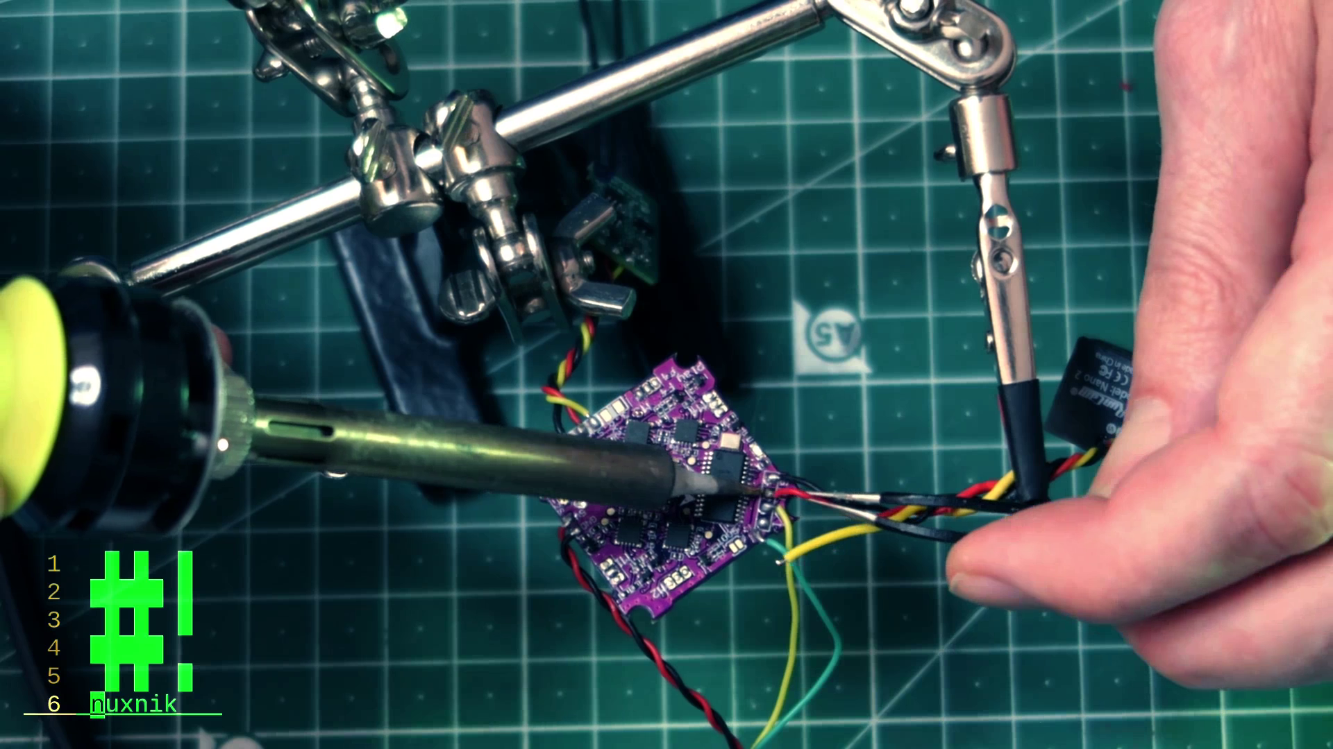
The last step is to solder the camera leads to the flight controller.
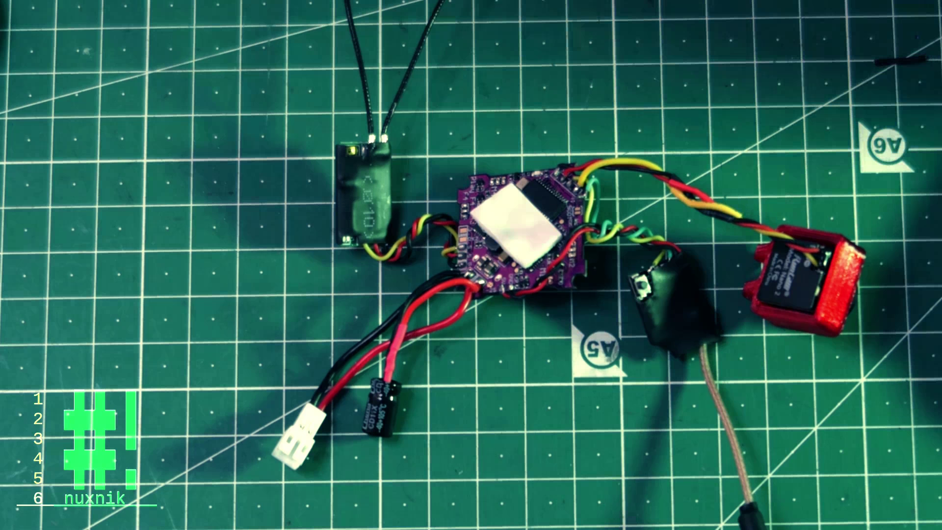
Heatshrinking and Insulating
Since the PCBs of the flight controller and the external modules are exposed, we need to insulate them from each other to prevent a short circuit. Let's wrap each external module in some heat shrink tubing. Later, we can conformal coat each board. I usually do this after I have done a test flight. So for now, we will insulate everything with heat shirink tubing.
For the receiver I cut out small areas to expose the binding button and the status LEDs.

The same process applies for the VTX
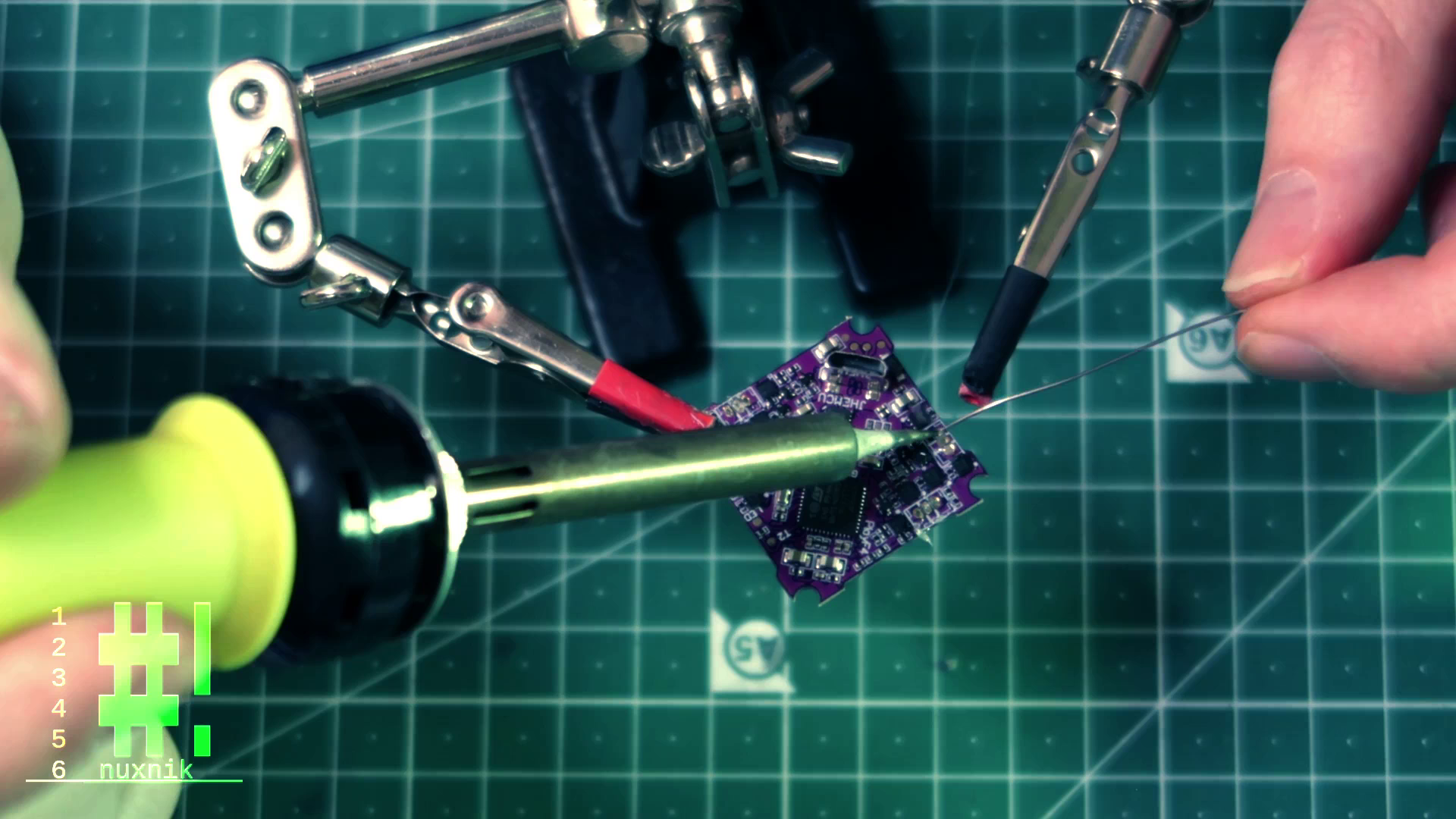
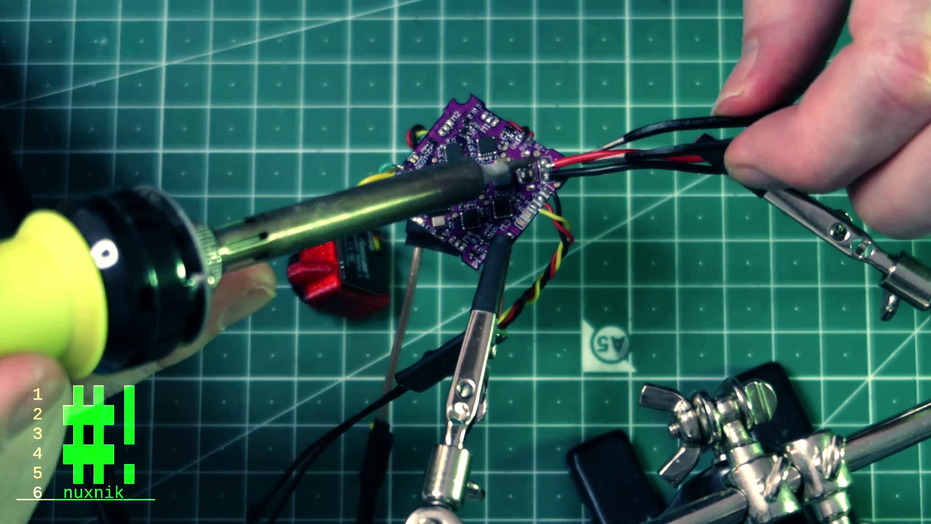
Wiring up the Power Lead and Capacitor
We can start by soldering the power leads to the flight controller. Important: Pay attention to the standard color convention:
- RED = Positive(+)
- Black = Negative(-)
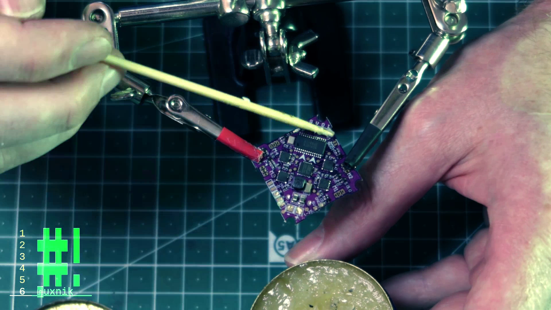
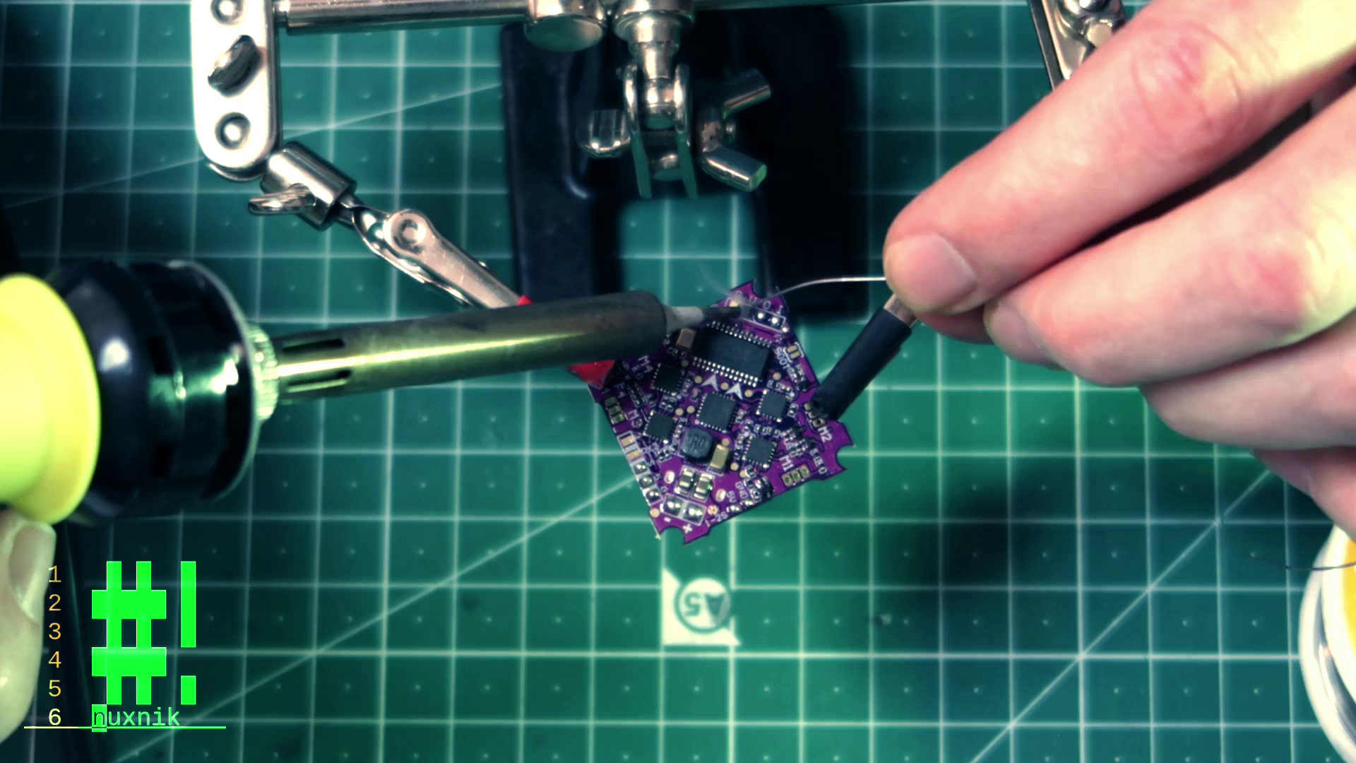
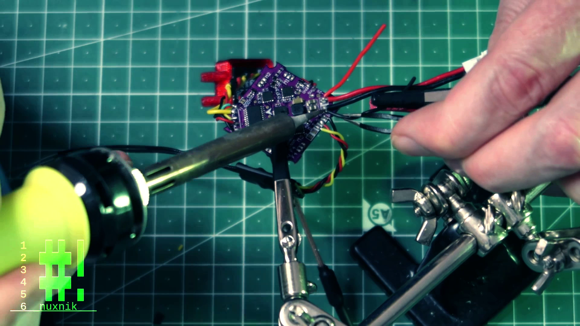
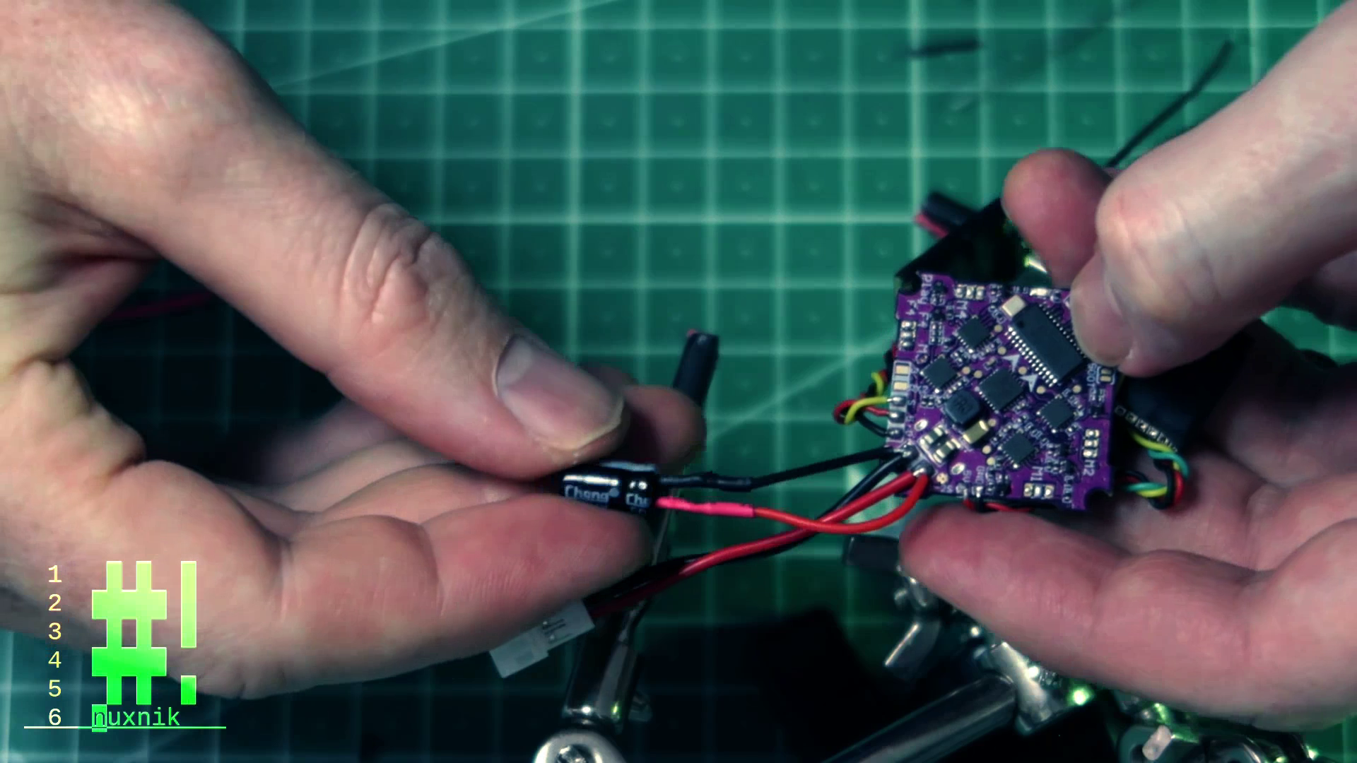
For the capacitor, we will be doing something a little different. The space is very limited inside the canopy of the drone. Since we aren't left with much space to work with, we will extend the leads of the capacitor with some silicone coated wire. This way, the electrolytic capacitor and be mounted outside of the canopy area. Let's start by soldering the extension leads to the flight controller. Note: each extension lead is approximately 30mm long. It is also important to follow the color coding convention mentioned above.
After the extension leads are securely soldered, let's connect the capacitor. We will be covering the exposed leads of the capacitor with heat shrink tubing. Before connecting, make sure to slide the heat shrink over the wire between the solder joint and the capacitor lead. Repeat this for both battery poles.
Important: Electrolytic capacitors are polarized components! This means you need to connect the correct polarity. The polarity of electrolytic capacitors is usually marked on the side of the capacitor. Another convention is that the longer lead of the two is negative.
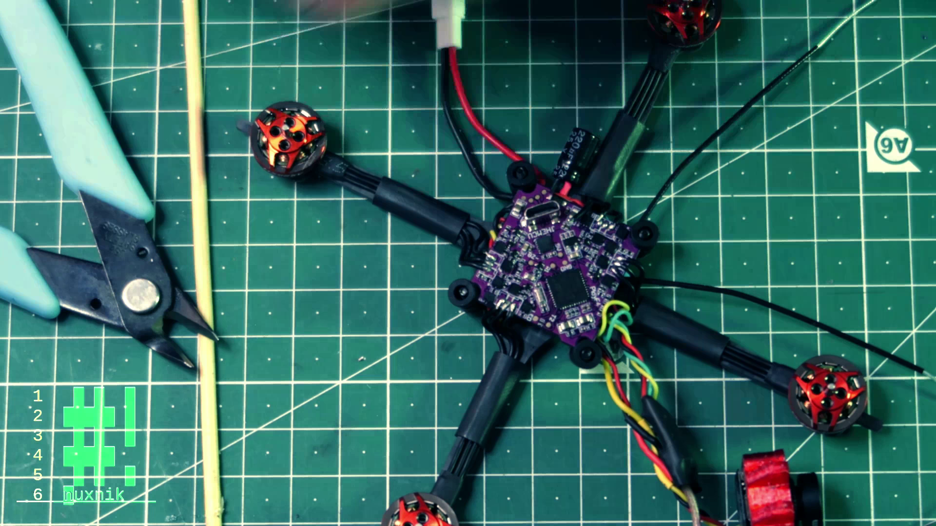
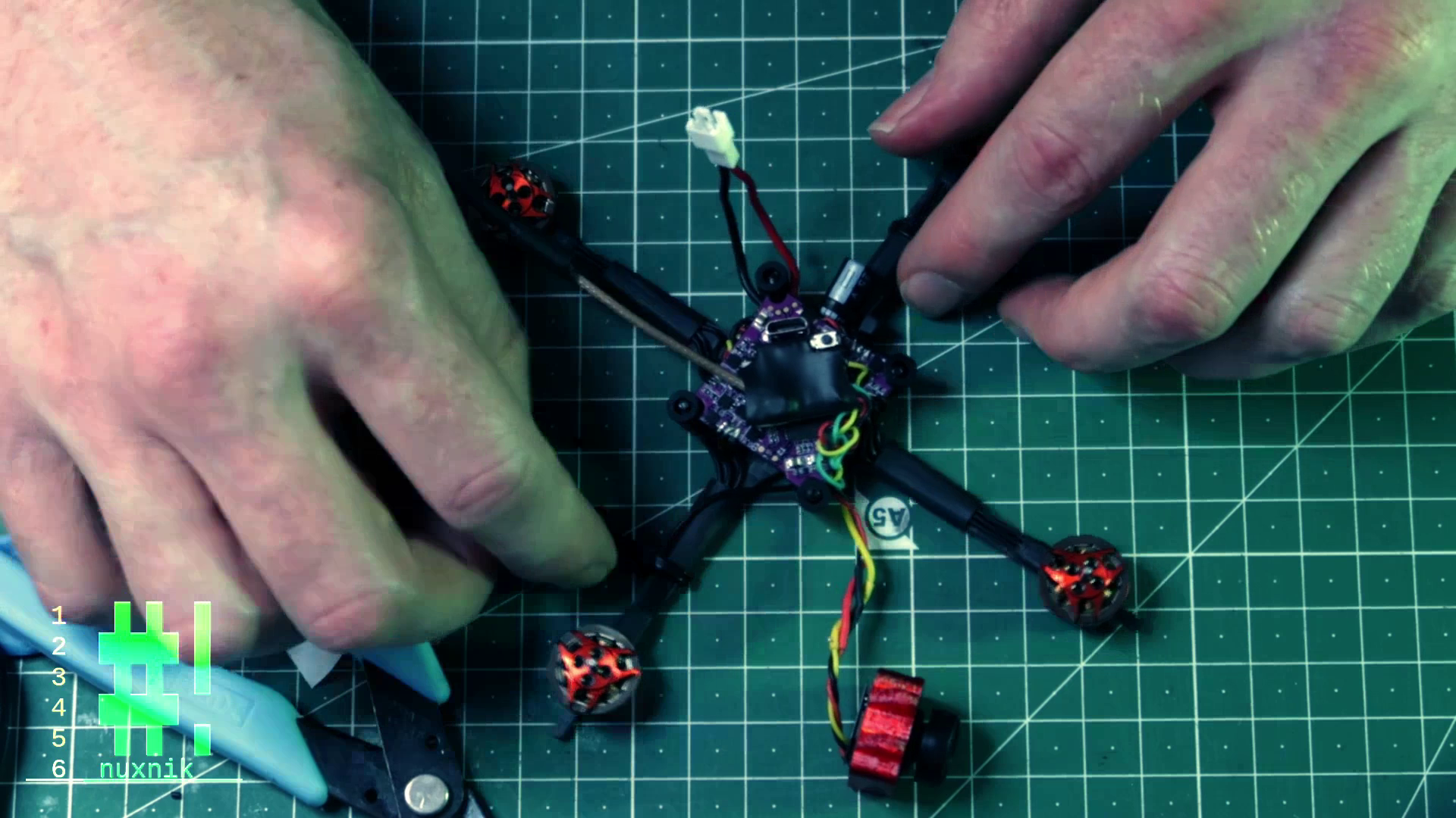
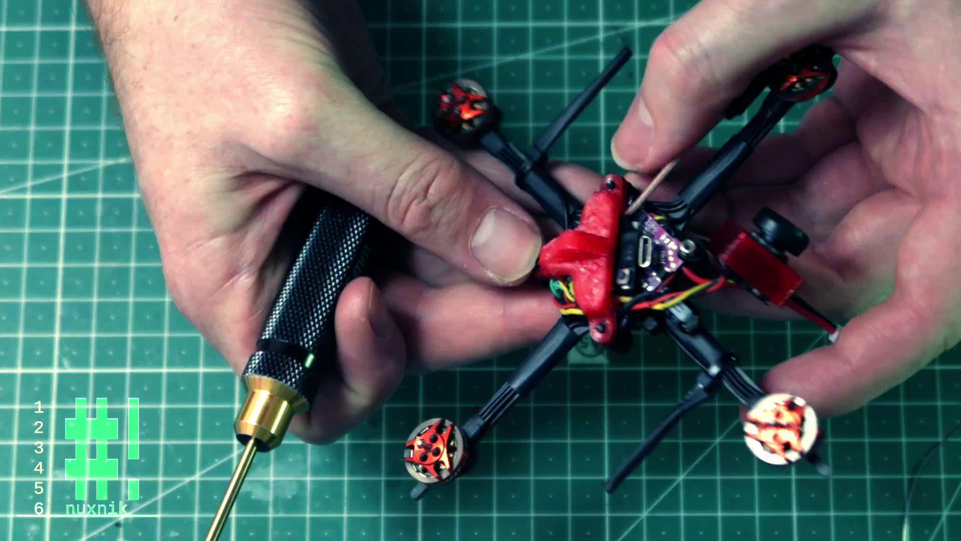
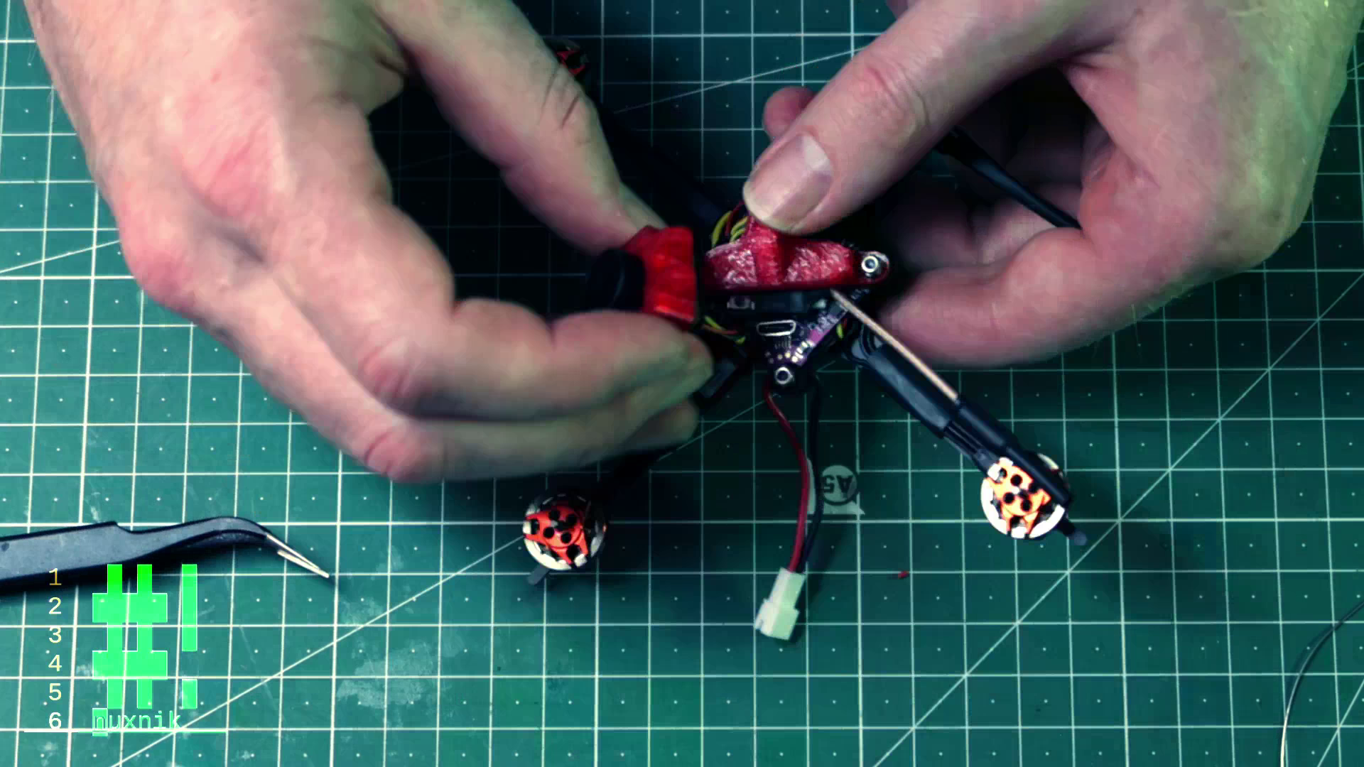
Wiring up the Motors
Before we can connect the motor wires, let's secure the receiver to the FC. We will use double-sided foam tape and secure the RX to the TOP of the flight controller.
Important: The top of the flight controller has a small arrow pointing forward. Remember this orientation and in which direction the arrow is pointing when mounting the flight controller to the frame. The arrow points in the "forward direction".
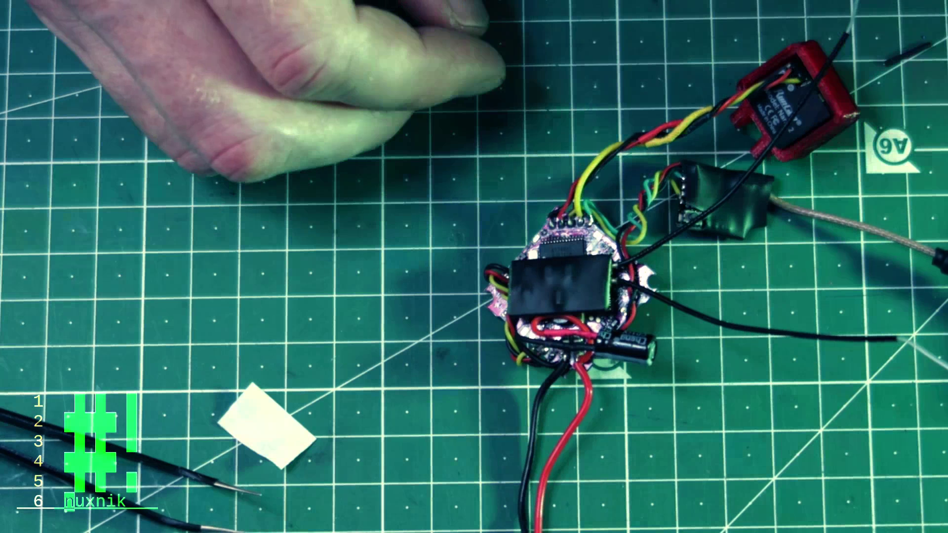
After securing the RX we'll add the rubber grommets and place the FC upside-down into the frame. Make sure the arrow is still pointing forward. We are doing this for the following reasons:
- The USB port of This flight controller is on the bottom.
- The frame is not designed for a USB port of this type.
This means, that our motor configuration and a few other paramters will need to be fixed. This is not a problem and we will correct it later in Betaflight.
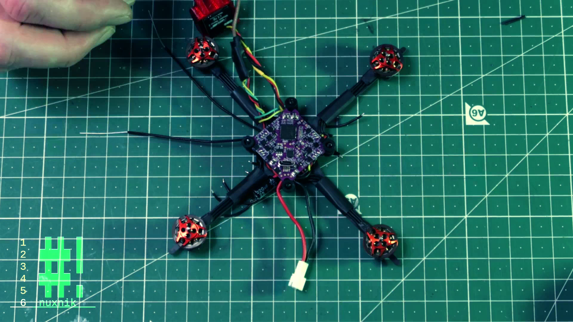
Measure the correct length for all four sets of the motor wires to the corresponding pads on the flight controller and snip off the excess.
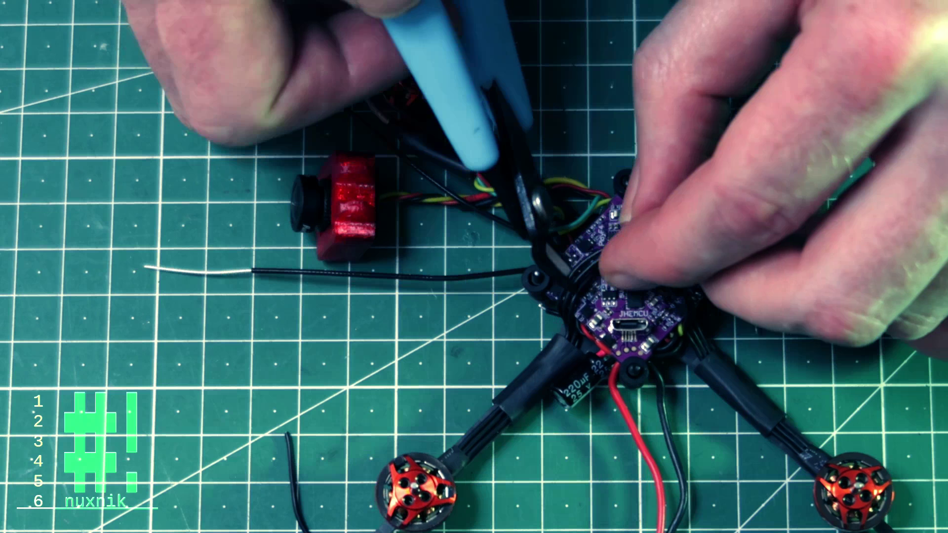
Add some flux, strip the ends of the wires, tin them, then finally solder them directly to the flight controller.
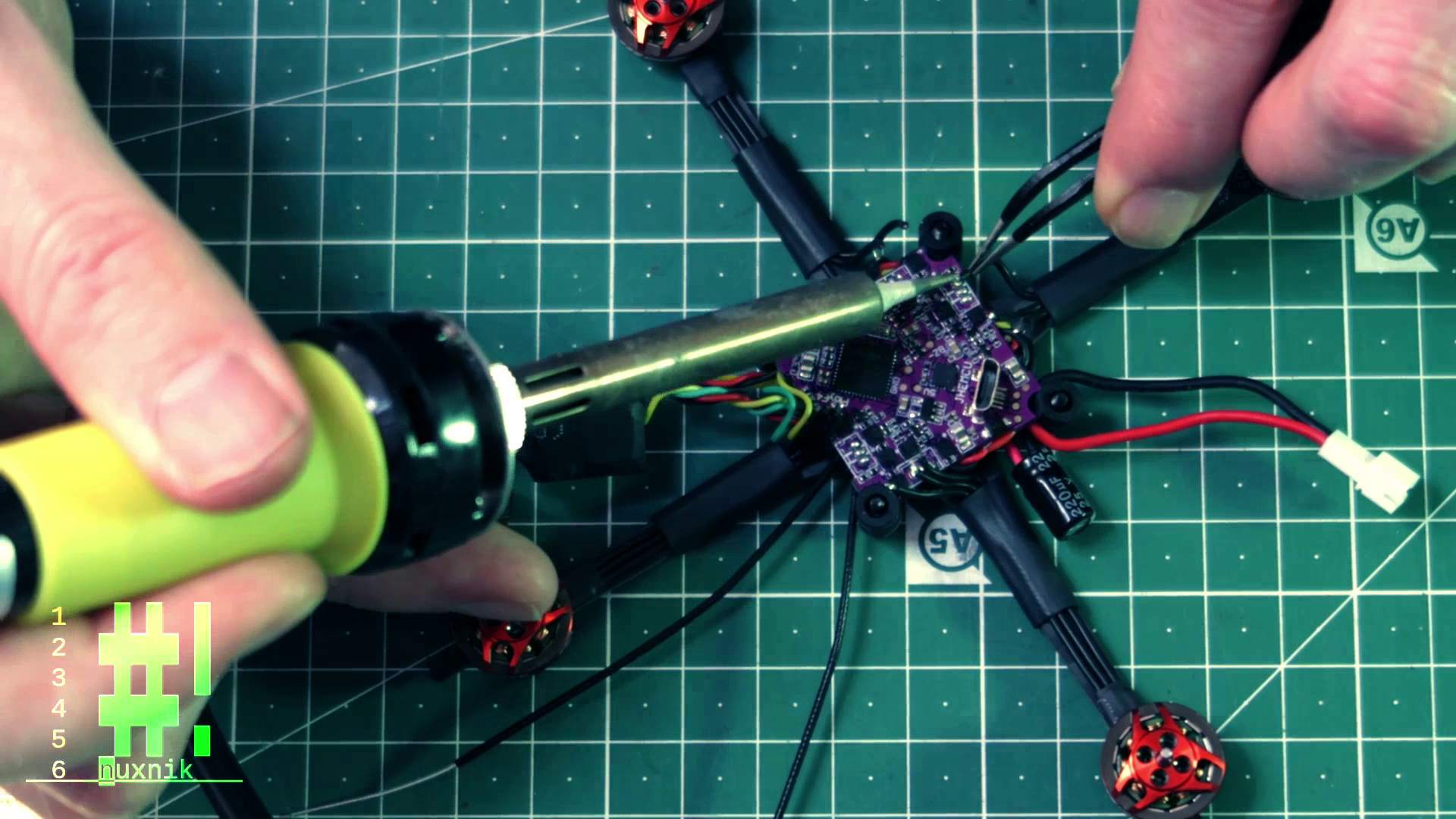
TIP: to keep the frame from sliding around your workspace, secure the frame with a piece of Blutac.
RX Antennas
For the RX antennas of the XM+, let's weave them through the frame so that each antenna points to an arm directly opposite the other one. We will use two zip ties and some heat shrink to secure them to the arms so that they stick out and get better reception.
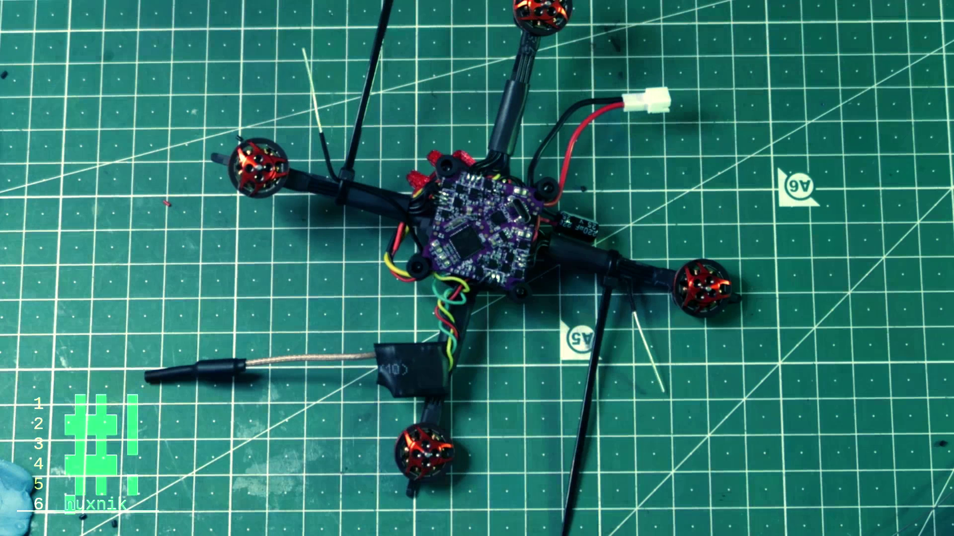
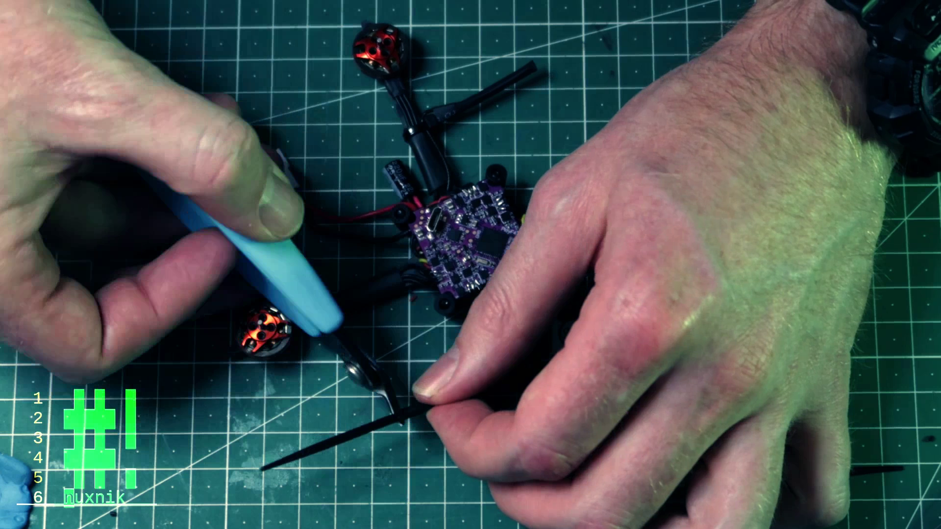
Tidy everything up and cut off the excess zip-ties protruding from the heat shrink. Be careful not to snip off the end of the antenna!
Since our zip-ties are already out, let's secure the capacitor to one of the arms. One zip-tie will do.
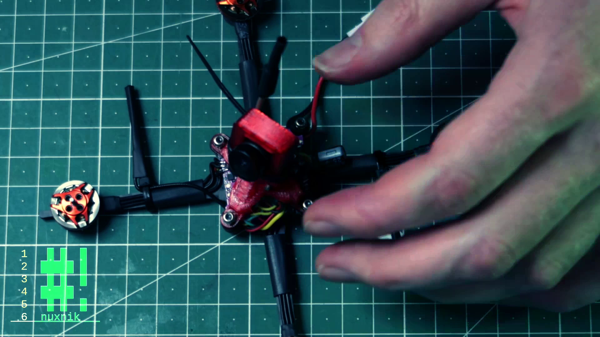
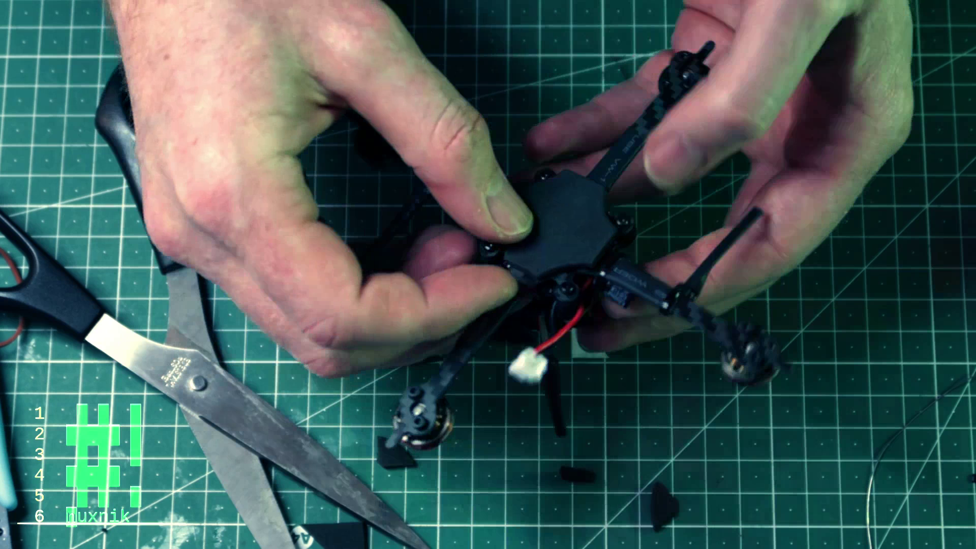
Canopy Assembly
Let's assemble the canopy! With the same double-sided tape we used with the RX, we'll attach the VTX to the top of the FC (formerly the bottom). Make sure that the VTX button is next to the USB port and has enough room so it won't be pressed after mounting the canopy.
Pull the wires of the FPV camera over the board and attach the bottom part of the canopy assembly.
Attach the camera to the 3d printed mount with the provided screw and nut.
Attach the VTX antenna to the camera mount with a zip-tie and snip off the excess.
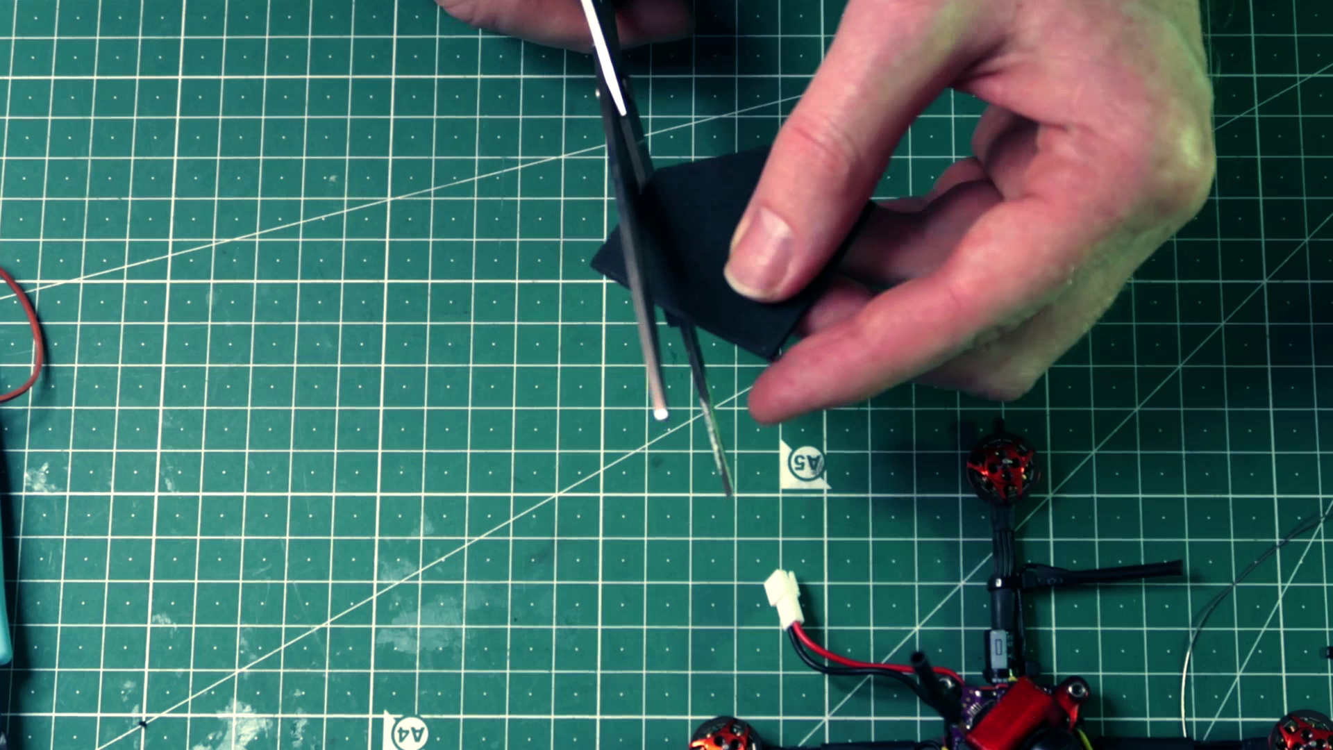
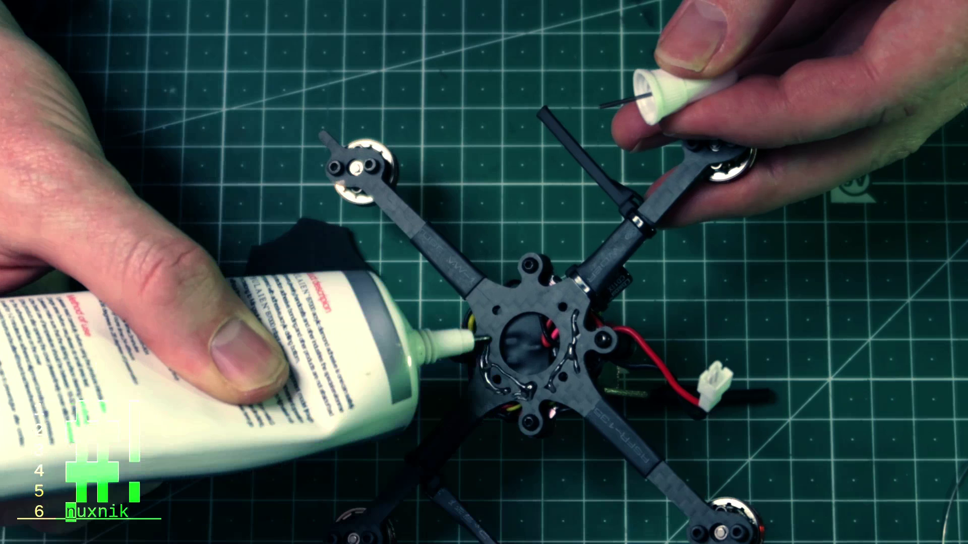
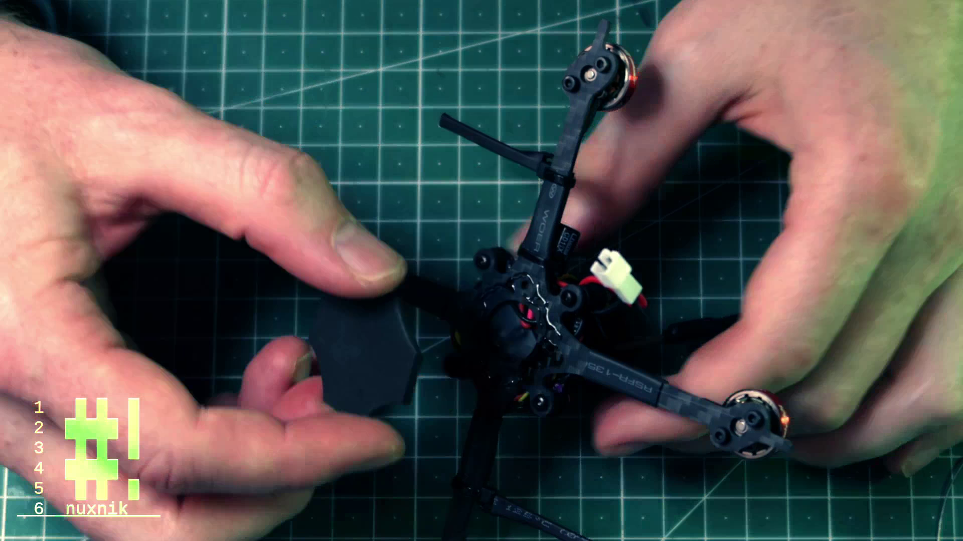
Finishing Touches
We're almost done! We have just a few more small things to finish. Add some rubber foam to the bottom of the frame to pad the battery and give it some grip when in flight. Measure out the correct amount of foam rubber and trim off the excess with some scissors. Glue it the the frame with some B-7000,if not some sort of rubber cement will do.
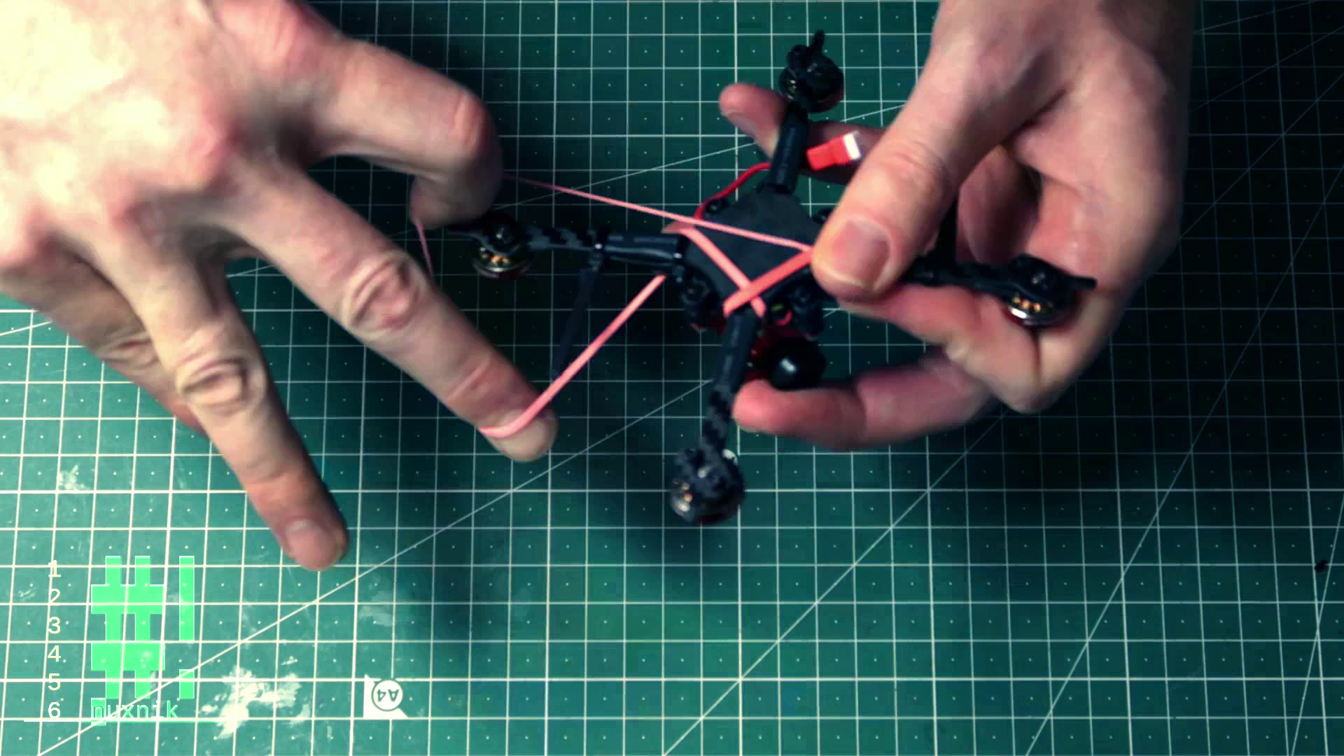
Add a rubber band to secure the battery.
Power it Up!
Now we can power it up for the first time! Before plugging it in, break out your multimeter and put it into continuity mode. Make sure to probe both poles of the battery connector to check for a short circuit. If your multimeter doesn't beep, you should be safe to plug a battery in.
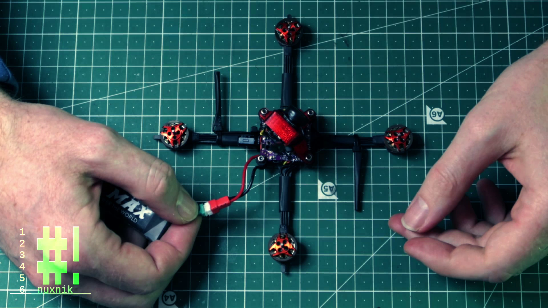
Important: Smoke = bad. If you see some smoke, unplug the battery as fast as possible and check your wiring with a multimeter. If you don't see any smoke and are greeted with a few beeps and some flashing LEDs - congratulations!
Build Video
For your convenience, I have created a build video based on this post. In the video, I cover every step of the build guide including some extra features. Check it out and while you're at it, subscribe to my channel.
Coming Next - Configuration
This is the first part of a series of articles about this build. In the next installment, we will configure our baby tooth in Betaflight, take it out to the field, tune it and do some test flights. Stick around!
Final Thoughs
This is an easy and fun build. The performance of this litte drone is amazing and has become over time, one of my favorites to fly. It is also a good starting point for people interested in building more complex drones. The wiring and configuration are straightforward and easy to follow.
I would like to thank KababFPV for the cool design.
Help Out
If this tutorial helped you in any way or you like what you read, send me some Satoshis and buy me a coffee. :)
12dxt1JsQnJhyhZPAr2b2xvzGyR9BgpncN
References
https://fpvcycle.com/blogs/build-guides-and-discussion/baby-tooth-1s-3