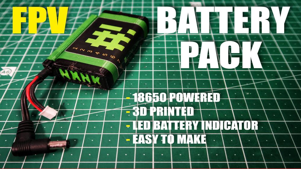
DIY FPV Goggle Battery Pack
Synopsis
For this project we will be making a simple DIY 2 series battery pack with a built in voltage indicator. We are going to 3d print the required parts and solder the rest of the components together. We will also be designing our own goggle battery enclosure and learning about battery packs in general. Sure, you can buy a battery pack online - but that's no fun. Nothing beats building your own stuff.
DISCLAIMER: We are working with live lithium-ion batteries and I am in no way responsible for a mistake on your part. Extreme caution should be taken that the wiring is correct. This can be dangerous if the battery polarity is crossed and can potentially start a fire. The least of your troubles, will be that you will ruin your batteries. Use good judgment, be careful and follow along at your own risk.
Bill of Materials
This project is basic and the required materials are relatively cheap. For those of you who are experienced builders of electronics projects, you might not even have to order anything other than the battery capacity indicator. Most of us already have some screws, wire, and heat shrink already laying around. If you don't have these materials, order them anyway! They are sensible items to have in stock and can definitely be used in future projects. Here our list of the items we will need in order to complete the project:
| Quantity | Component | Price |
|---|---|---|
| 1 | 20 AWG Wire | 0.00€ |
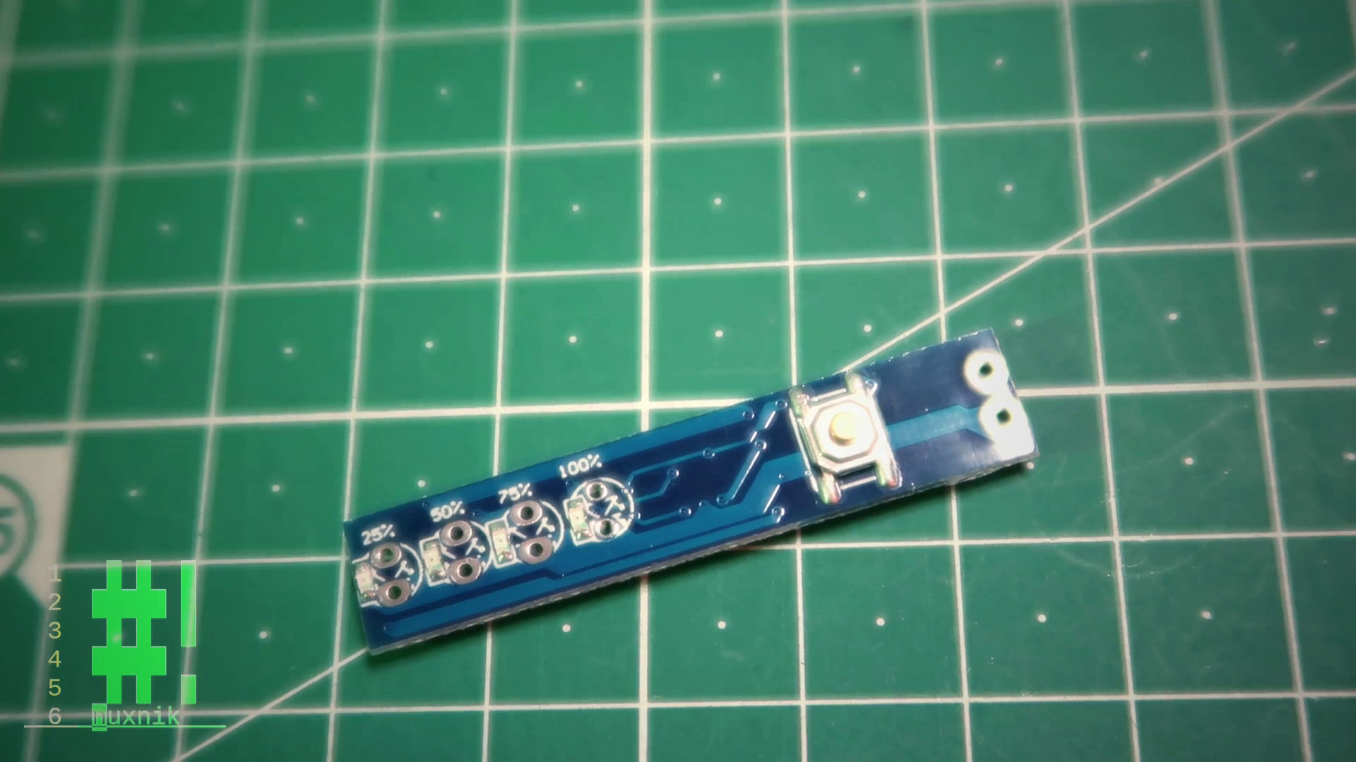
| 1 | Lithium Battery Capacity Indicator Module | 2.00€ |
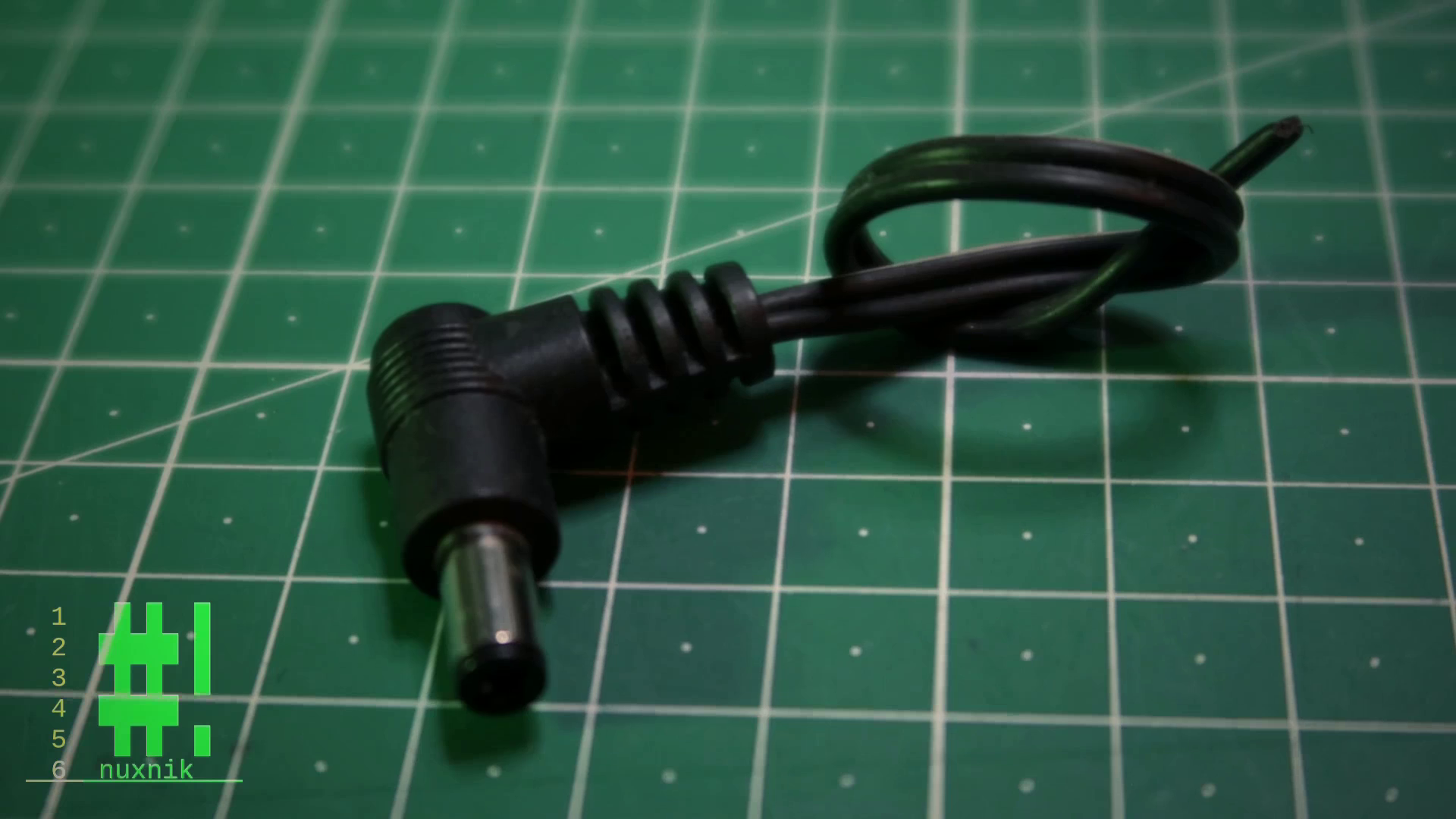
| 1 | 5521 Male Power Plug | 2.00€ |
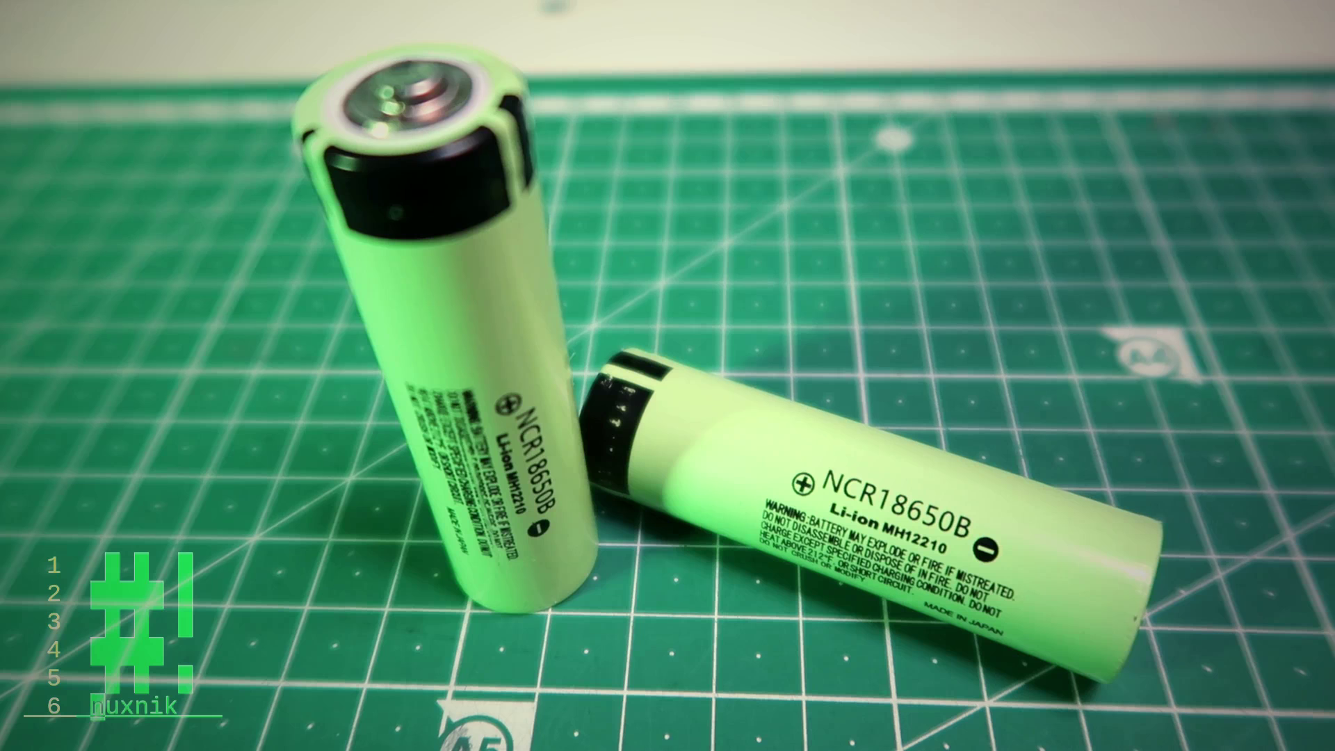
| 2 | 18650 Cell | 10.00€ |
| - | Heat Shrink | 3.33€ |
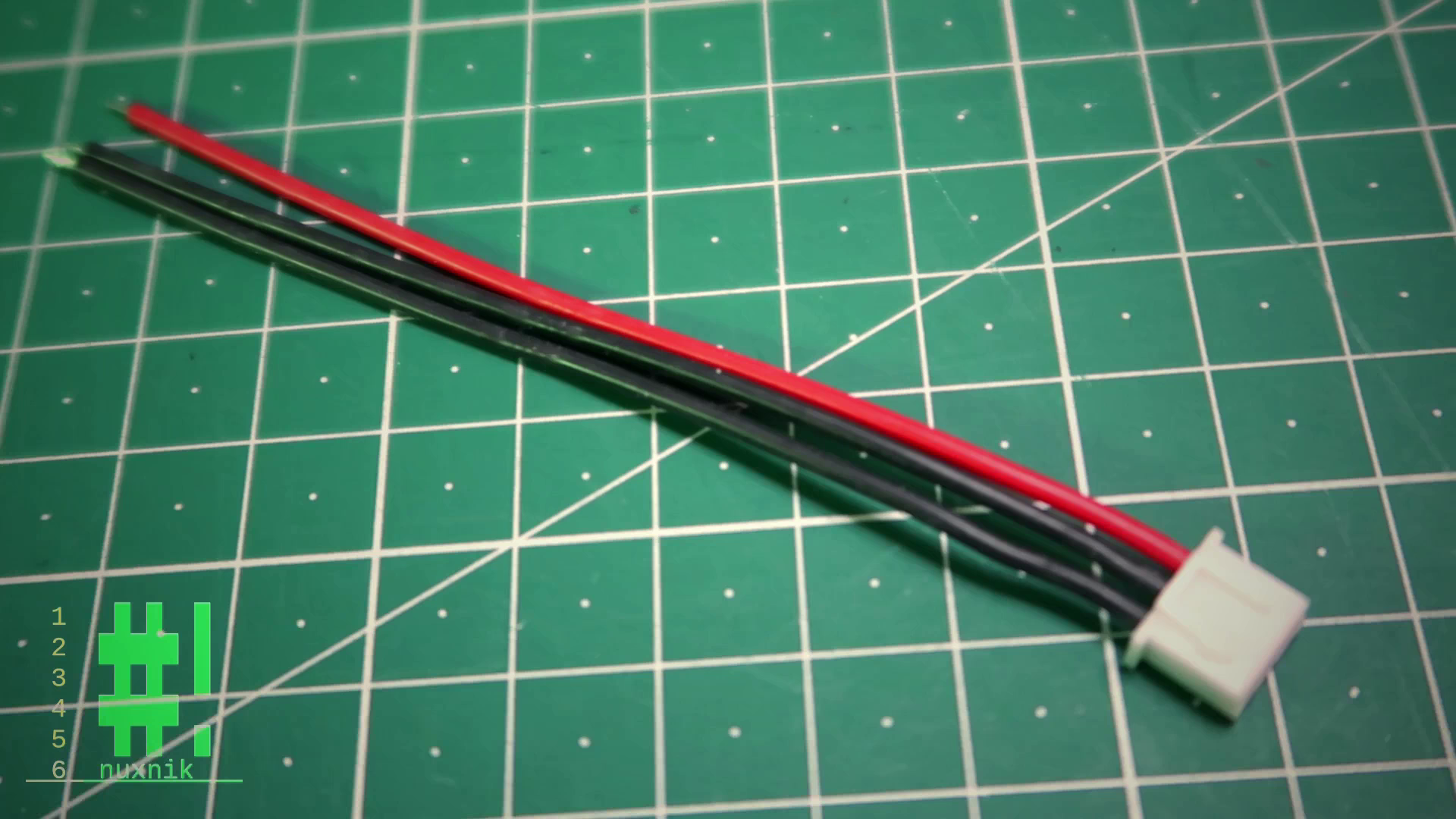
| 1 | 2S Balance Lead | 5.00€ |
| 4 | M2 screws | 0.00€ |
| - | 3D Filament | - |
| Total: | 22.33€ |
Keep in mind, it is also better to order a few extra items, so that you can make more than one. You can always use an extra battery pack.
Tools
Here are the minimal tools required for this build include:
- 3D Printer - if you don't have one, go to your local Maker-Space. Some libraries also provide 3D printers.
- Soldering Iron
- Screwdrivers
Additional and optional tools include:
- Hot air gun - for heating up shrink tubing
- Helping hands - if you don't have this, order it today!
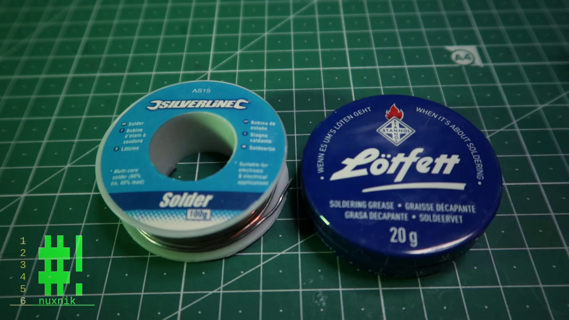
- Soldering Flux
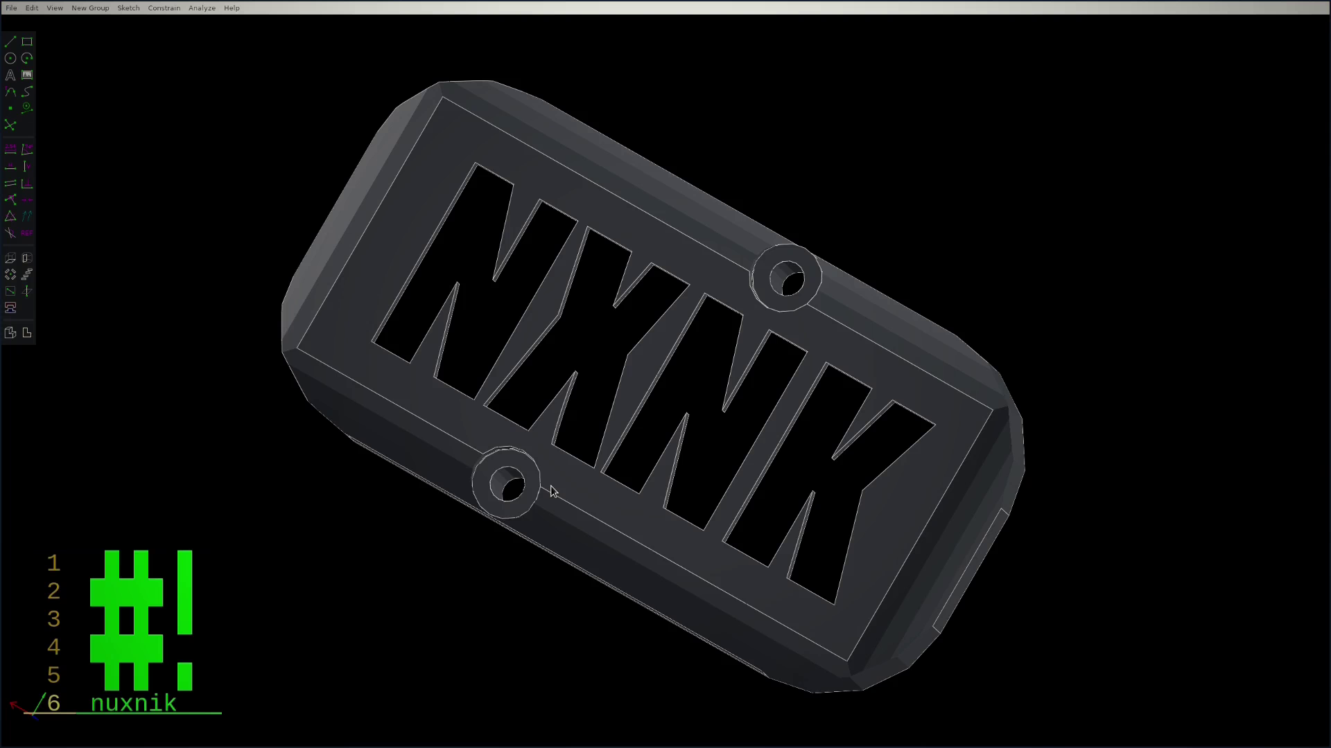
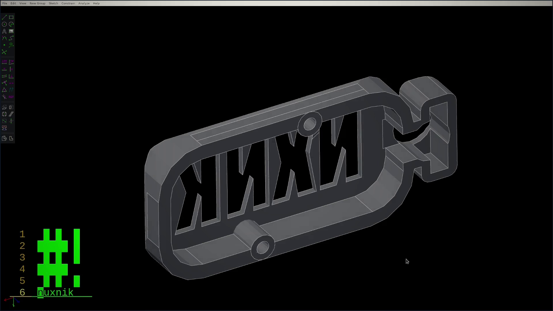
Design
For this project, I designed my own battery holder in SolveSpace. You can clone the repository directly from my GitHub page or download the printable STL files from the project page on Thingiverse.
If you are interested in directly modifying the files, download SolveSpace and give it a try. It is very easy to learn, intuitive and most importantly free and open source. If SolveSpace is new to you, check out this excellent SolveSpace video tutorial series by Eric Buijs to get your feet wet.
Assembly
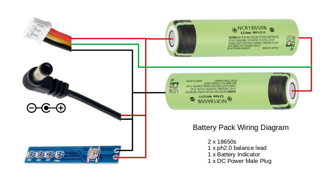
Assembly of this project is simple. The batteries in the pack will be connected in series giving us a 2S battery pack (8.4V fully charged).
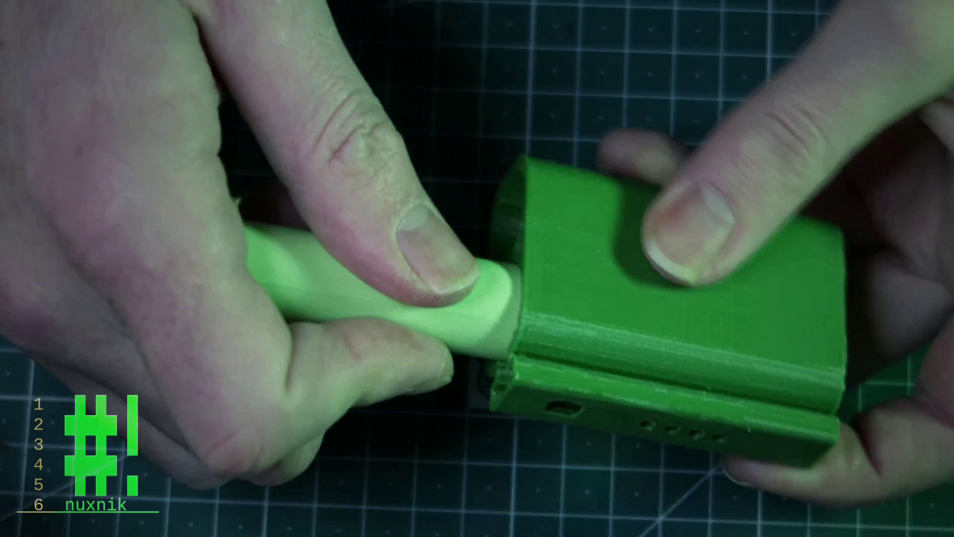
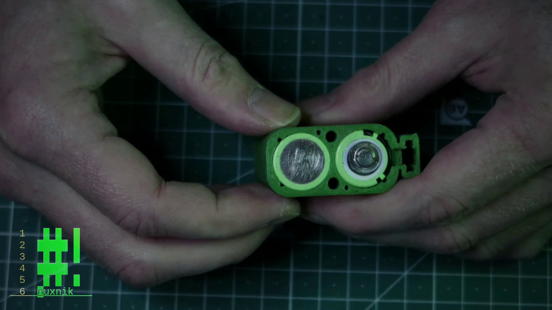
Inserting and prepping the 18650s
Since we are connecting the batteries in series, you need to insert them so that one positive terminal is peeking out on each side.
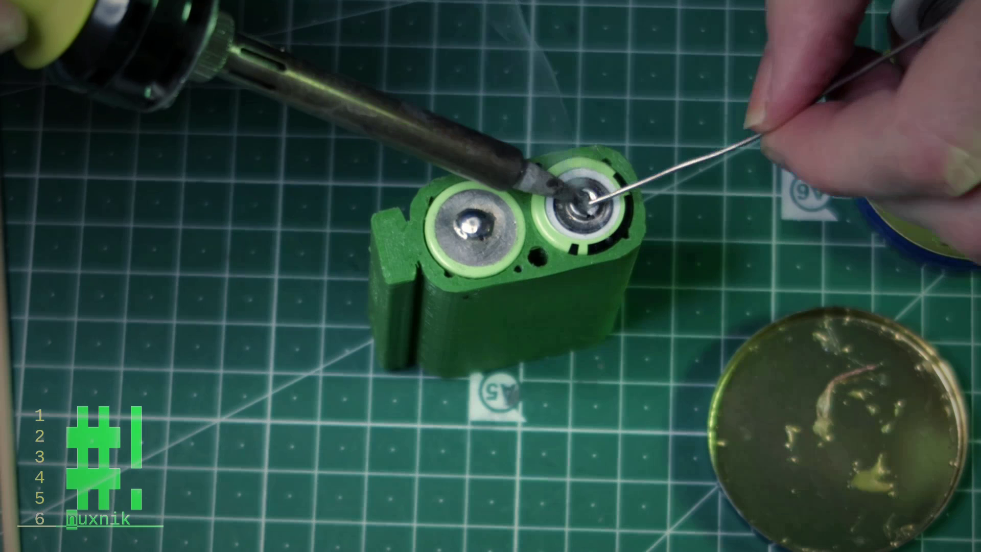
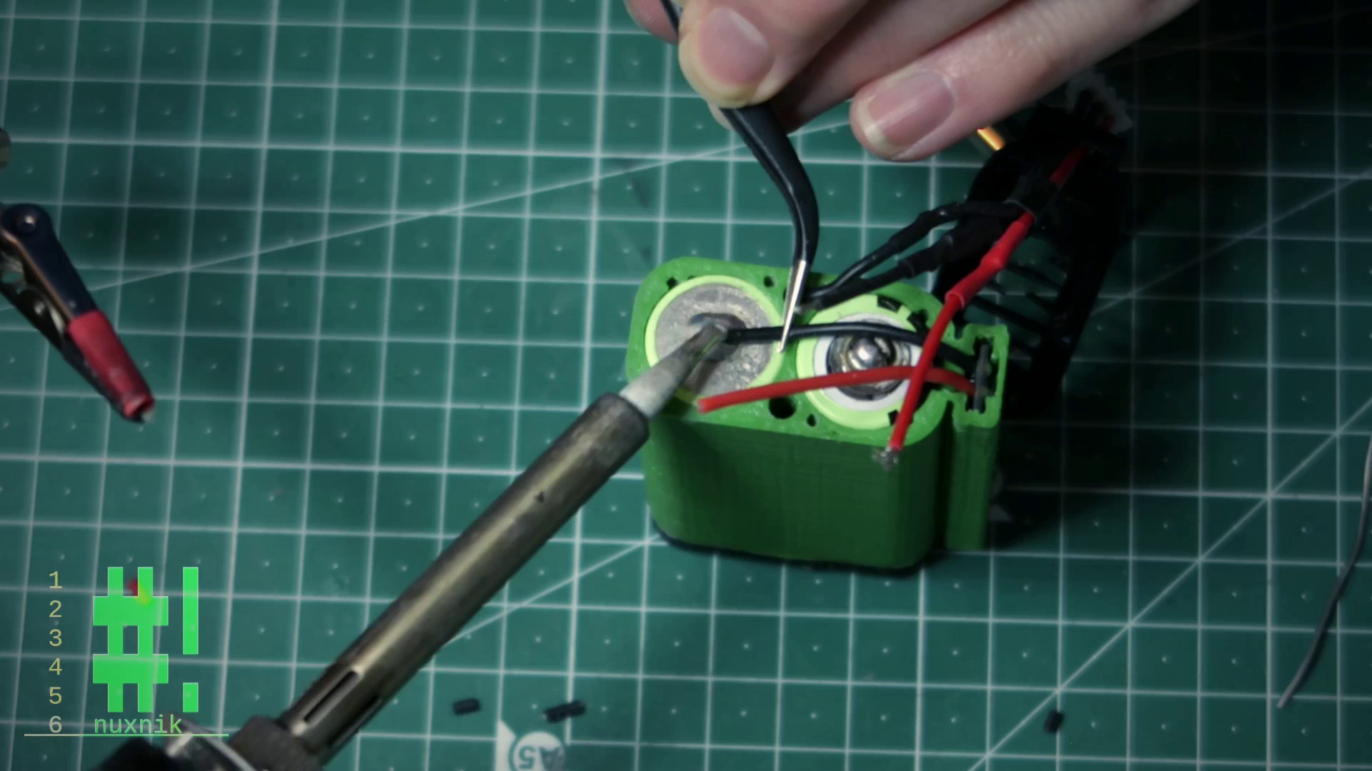
In order to make it easier for the solder to "stick" to the battery terminals, you will need to sand the all the terminals with some rough sandpaper. This is make it easier when we get to soldering. Turn your soldering Iron up to ca 400° C and add a liberal amount of flux to the sanded terminals. CAUTION! Do not touch the hot soldering iron to the terminals for more that ca. 5-8 seconds at a time. Let the battery cool before applying heat again. Overheating can damage the battery and potentially cause a fire. Use extreme caution.
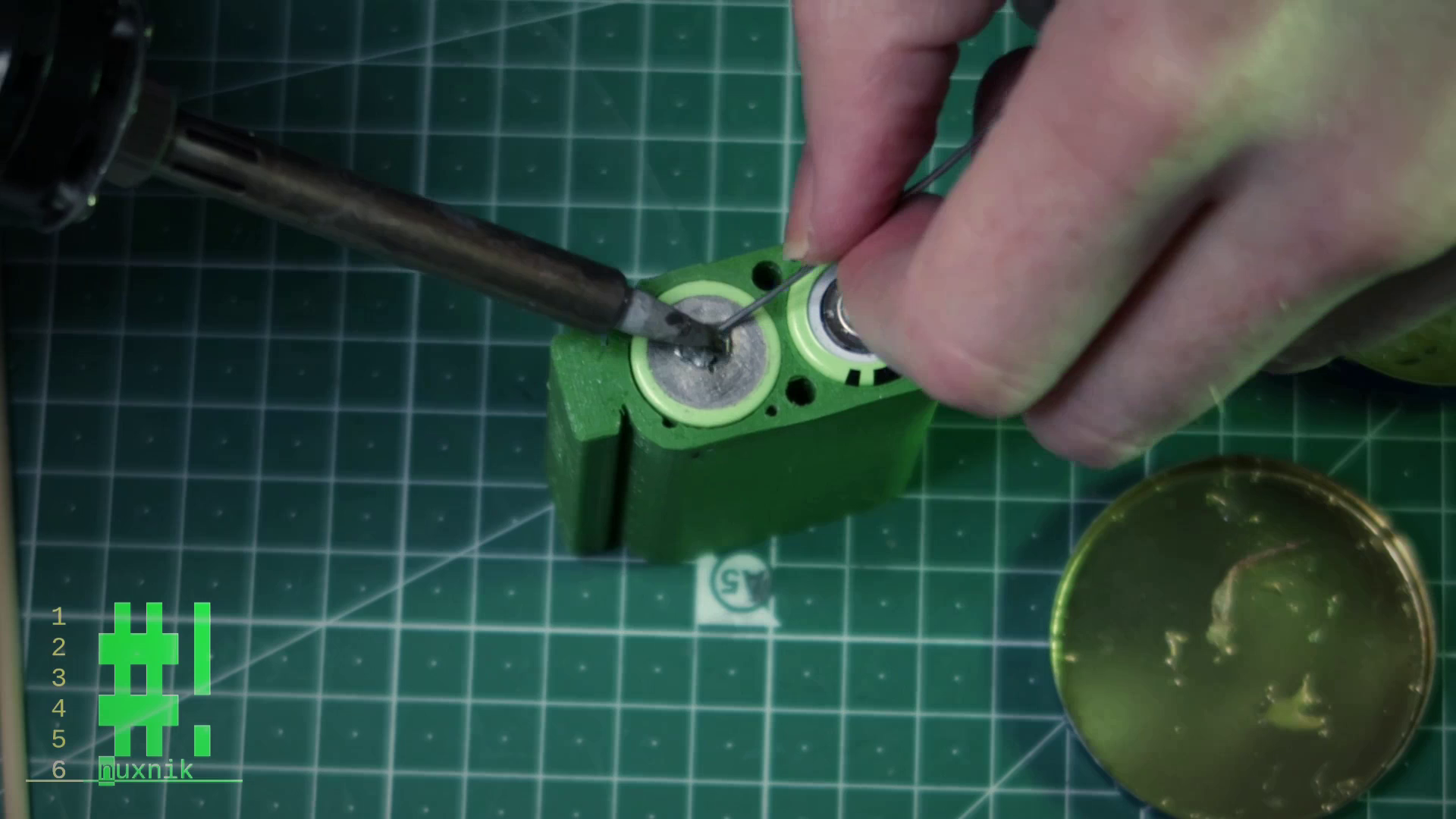
For the positive terminal of my specific batteries, I have left the small metal tab on the top, so as to make it easier to remove the solder later, should I want to re-purpose the batteries for something else. If your batteries don't have a metal tab, don't worry, just apply the solder directly to the terminals.
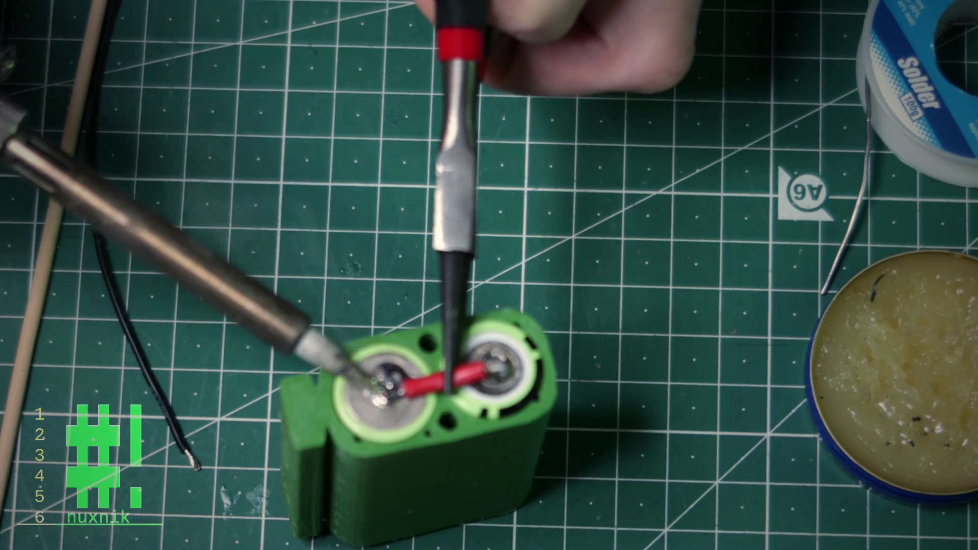
Connecting the Terminals
For this step you will need a small piece of 20 AWG wire, cut to approximately 2.5 cm. Flip the enclosure over and on the bottom side. This is the side where the voltage checker slot is closed. Heat up the terminal and solder the wire securely into place. Be careful of cold solder joints and make sure the wire is completely submerged into the blob of solder. Word of caution: Make sure to use tweezers or pliers when holding the wire into place. This wire will get blistering hot (pun intended) while holding it in place.
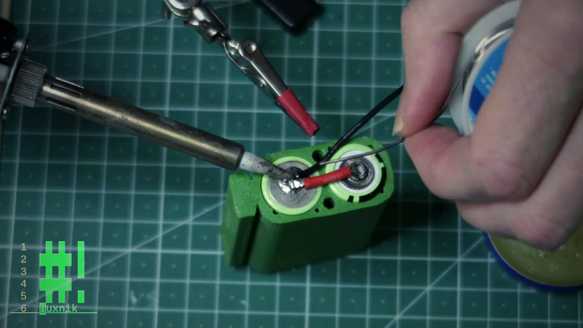
Balance Lead
We will now connect the balance lead. This lead is important for the battery checker to be able to measure the voltage of the first cell in the series. Click HERE to understand how this concept works and how it is used to balance the batteries in your pack.
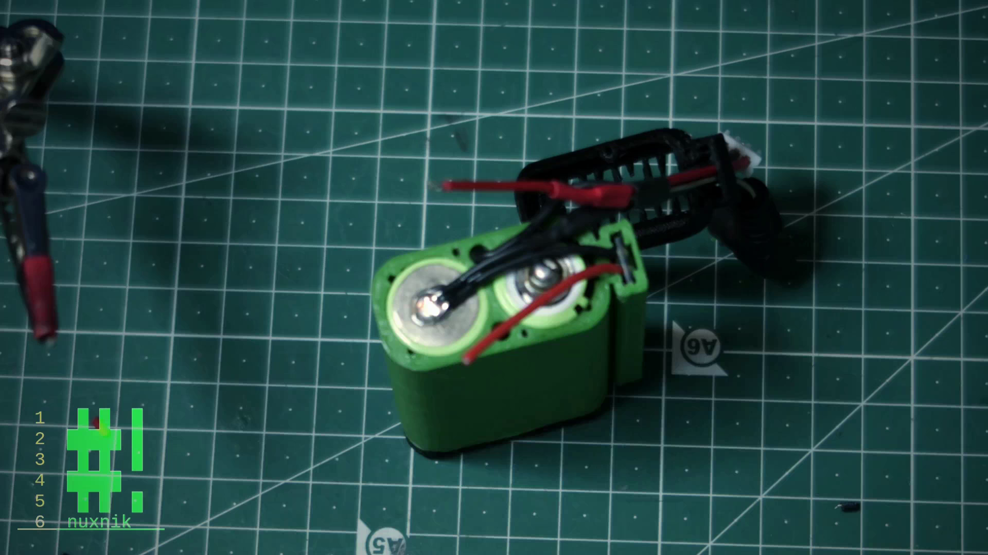
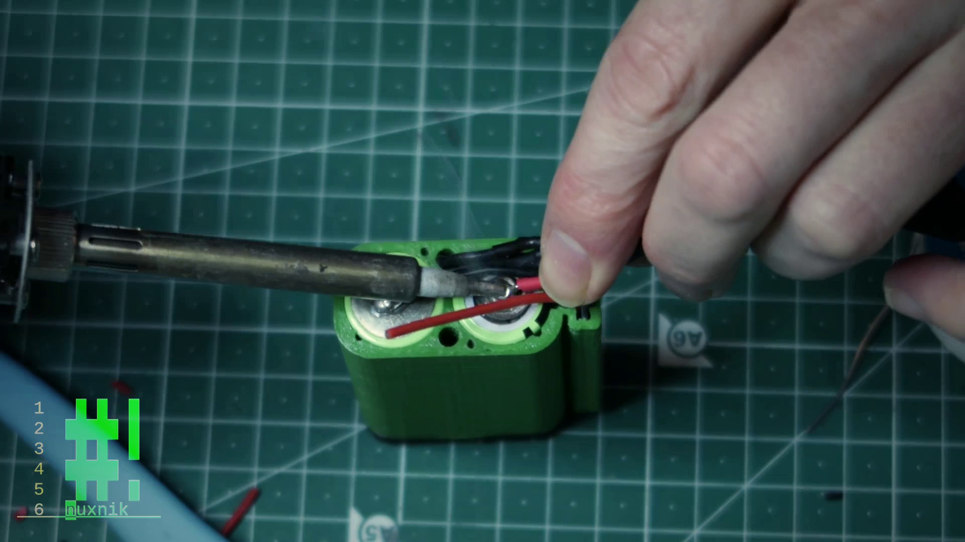
The balance lead should be soldered to one of the terminals. Afterward, feed the wire through the provided hole in the enclosure to the other side. In order to avoid short circuits, cover the end of the balance lead with some tape.
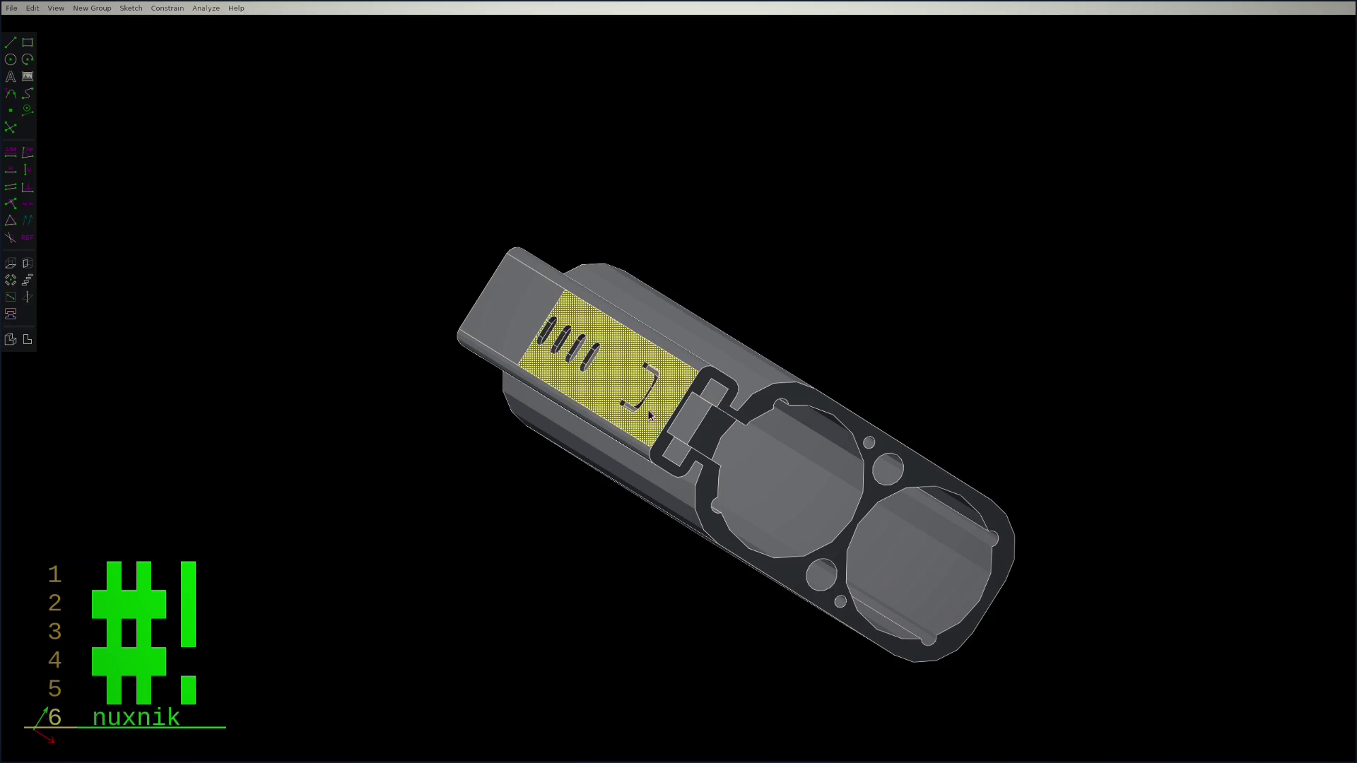
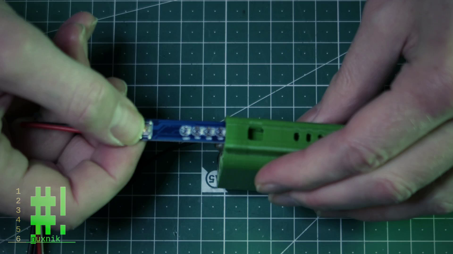
Battery Indicator
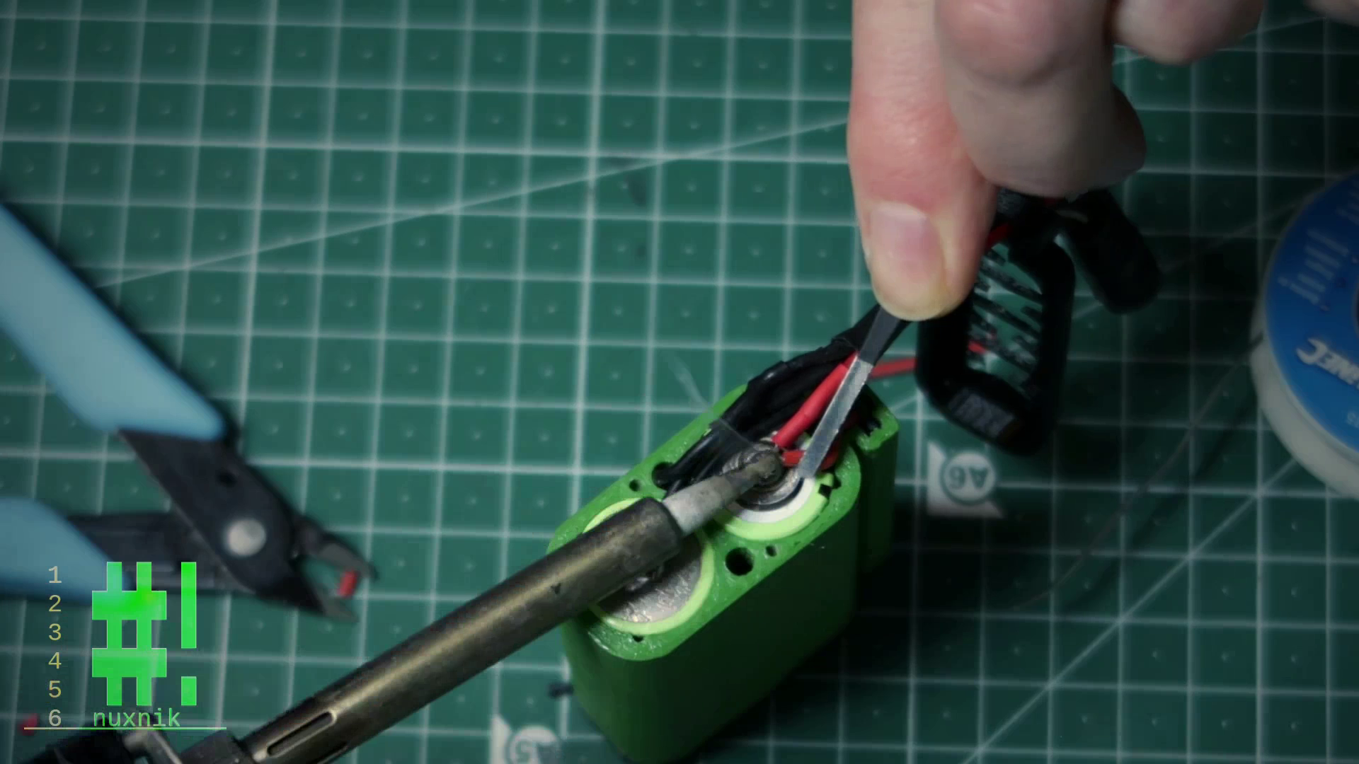
Now, let's add the positive and negative leads to the battery indicator. Add a little solder to each pad and pre-tin the leads.
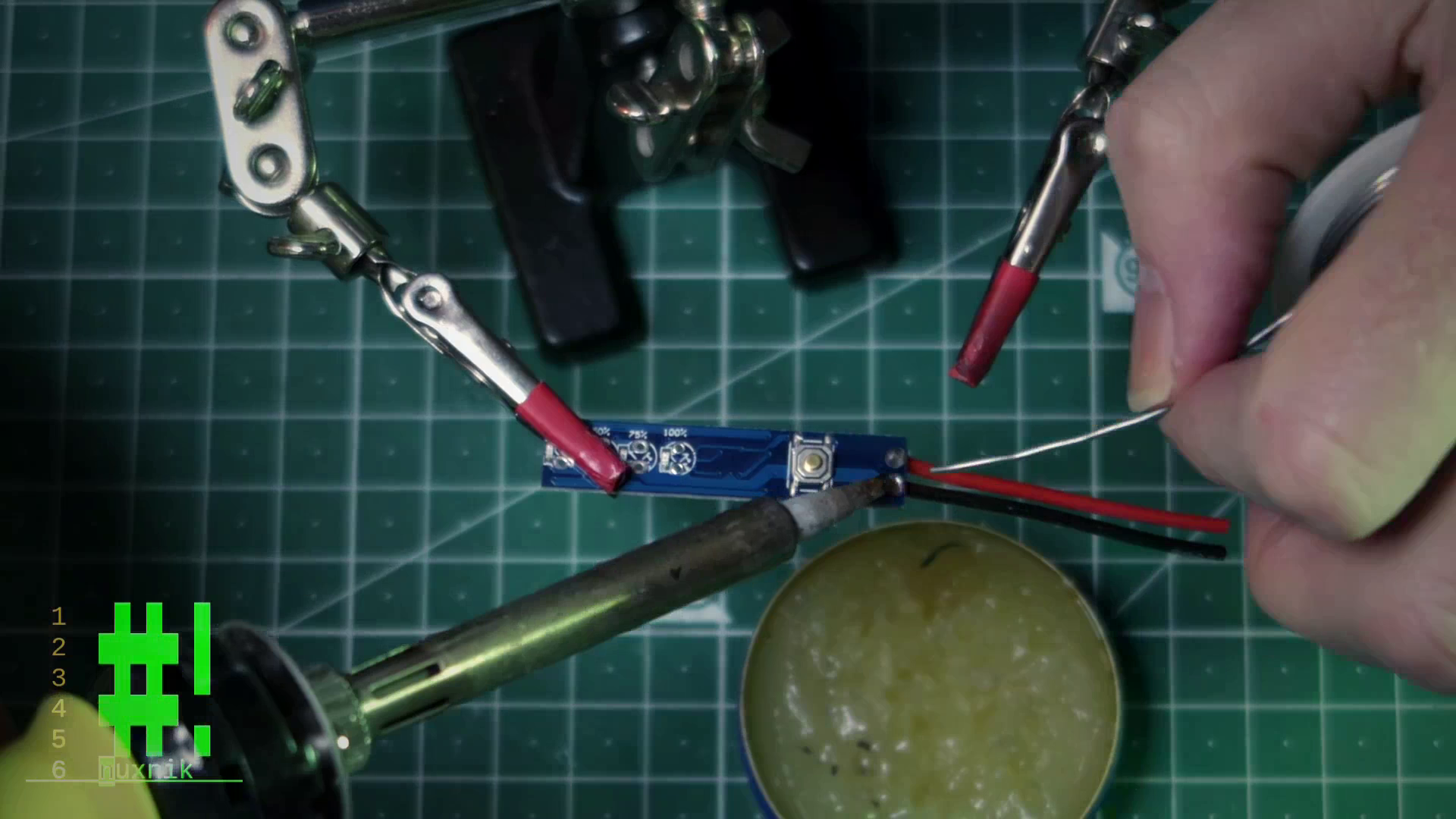
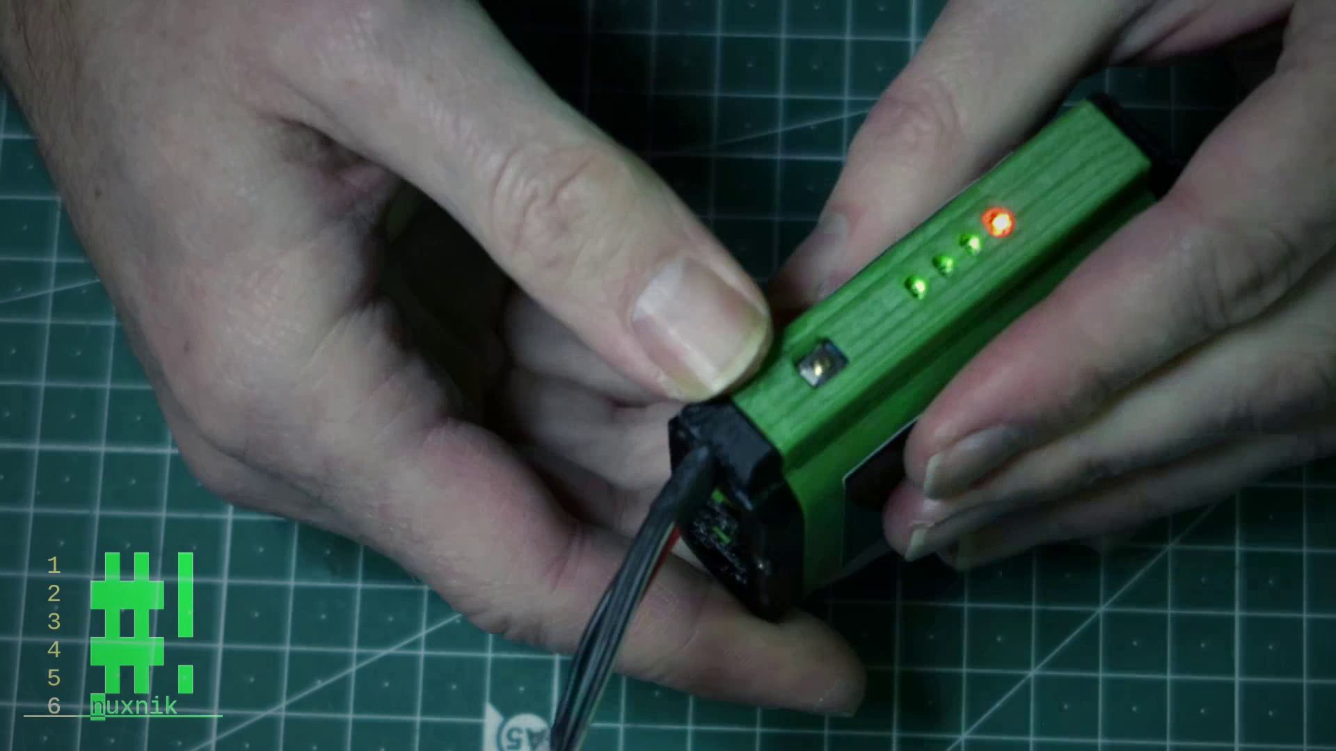
Next, we will insert the battery indicator into the slot of the battery body enclosure. Before sliding it in, hold down the button on the battery indicator so it can slide underneath the slot.
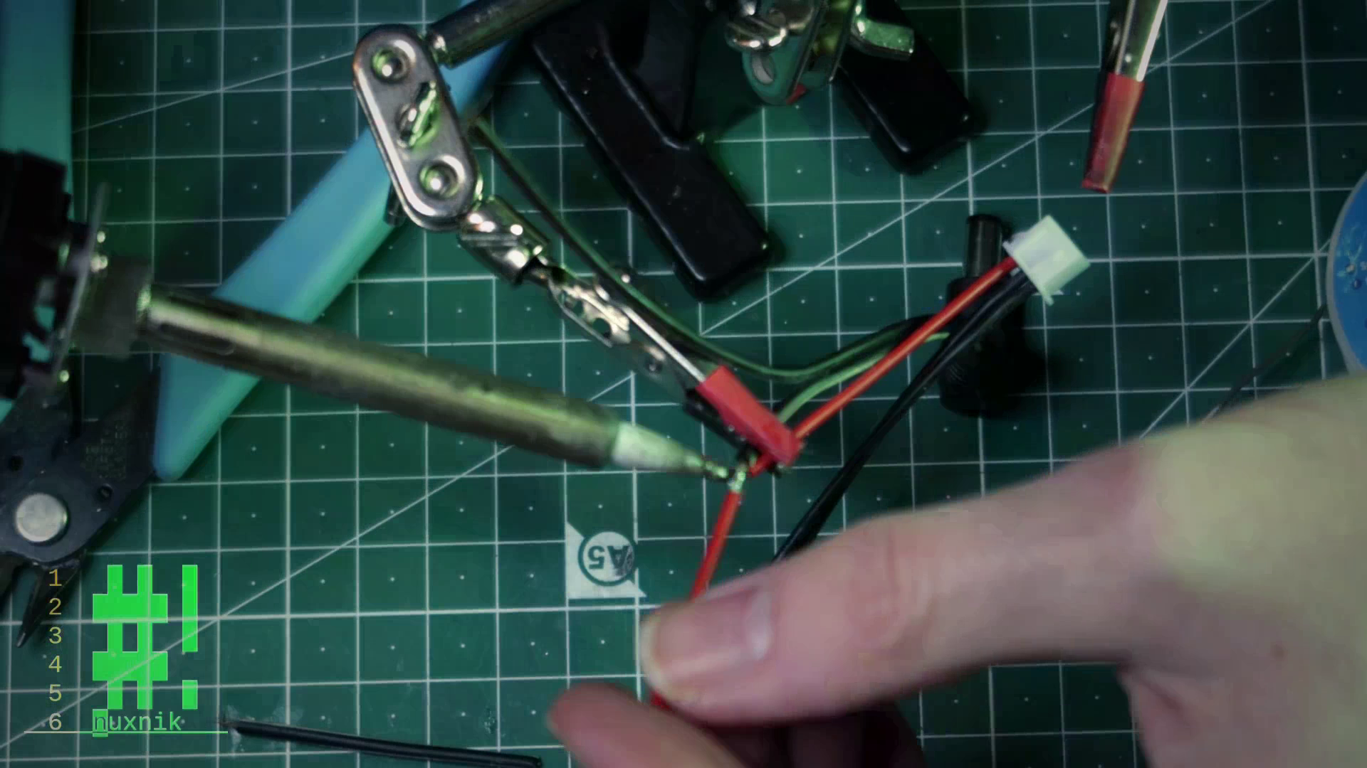
Joining the Leads
We will be joining the wire leads together for the remaining wires. Refer to the wiring diagram above for detailed information.
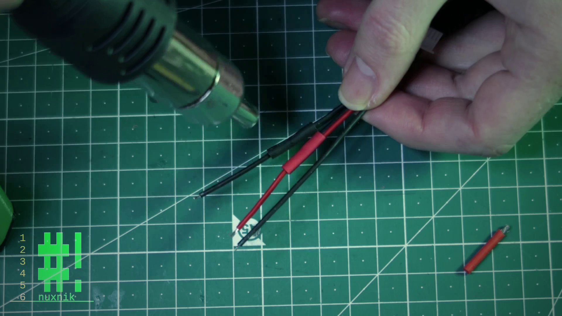
All positive leads will be reduced to a single one. The same goes for the negative leads. Strip the wires, add some flux and connect the wire together. We will use some heat shrink in order to insulate the exposed solder joints.
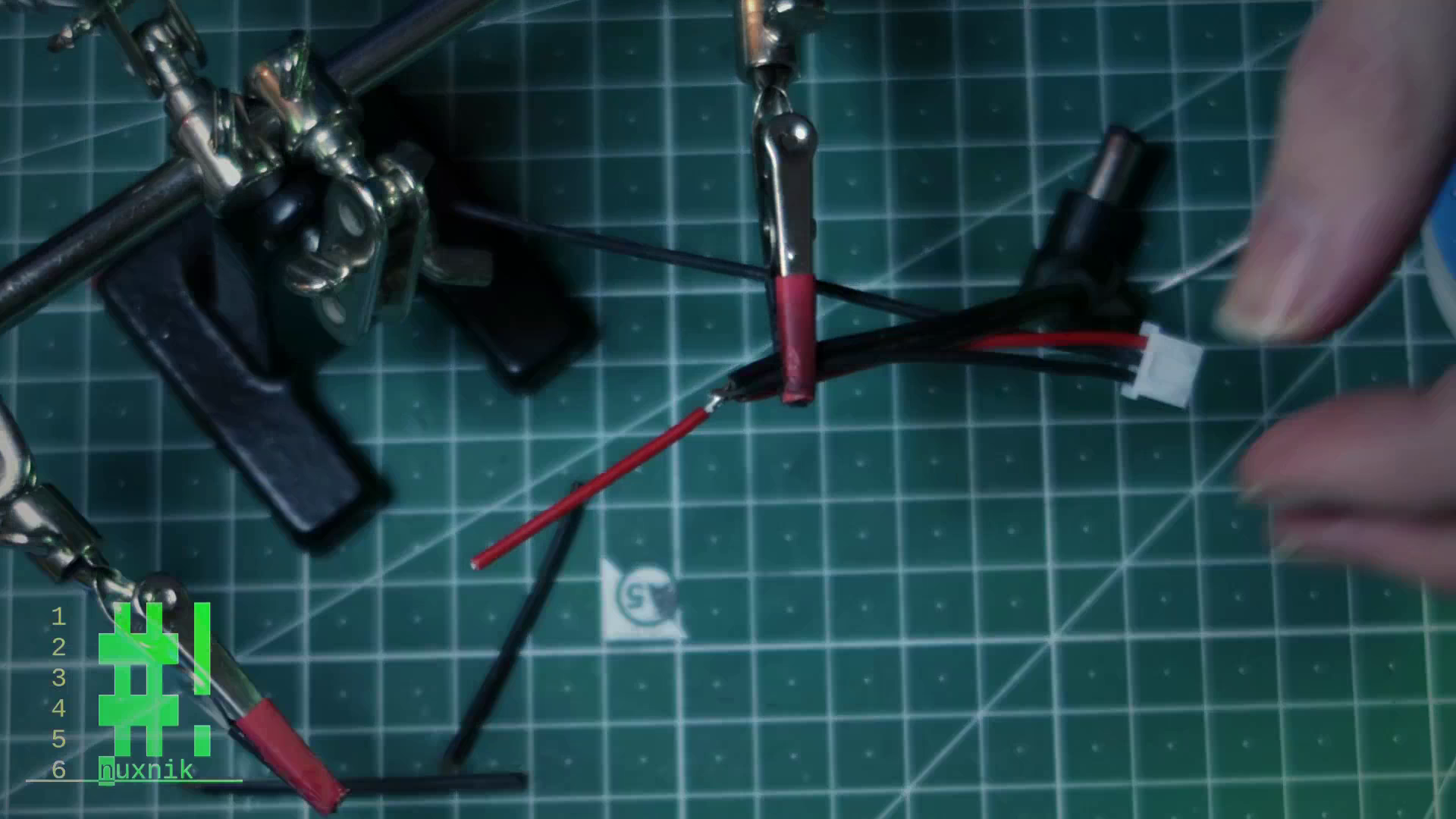
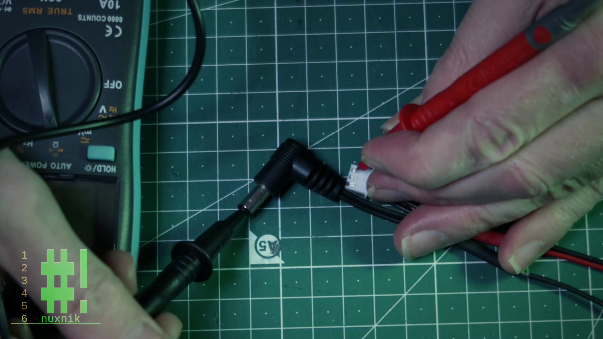
IMPORTANT: Before connecting the wires to the battery, get a multi-meter and check the continuity of each of the leads. Make sure the wires aren't crossed and that the polarity of each lead is correct - then double check just to be 100% sure.
Final Assembly
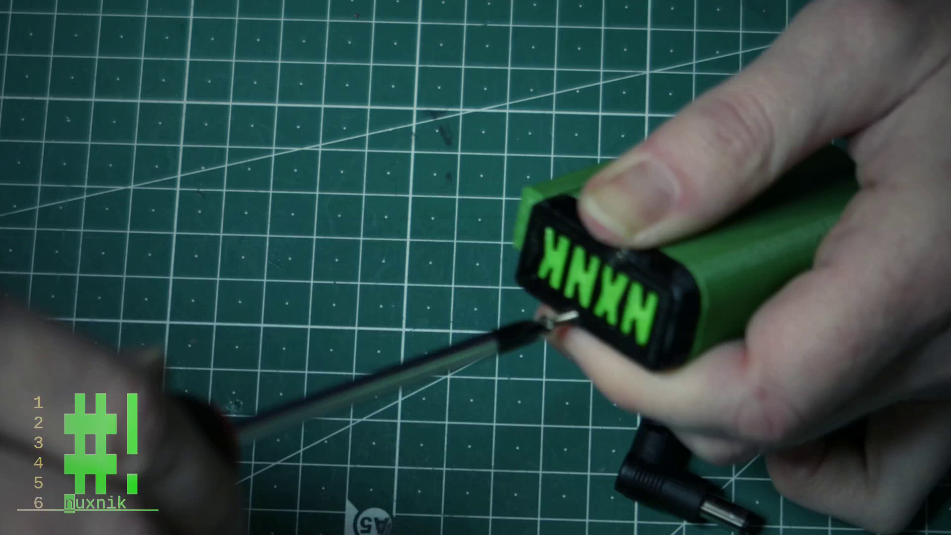
For the final steps in the assembly, feed the enclosure top through the corresponding hole an slide on an appropriate amount of heat shrink. Firstly, we will solder all the negative wires to the negative battery terminal.
TIP: Cover all exposed positive wires and terminals with tape to avoid a short circuit.
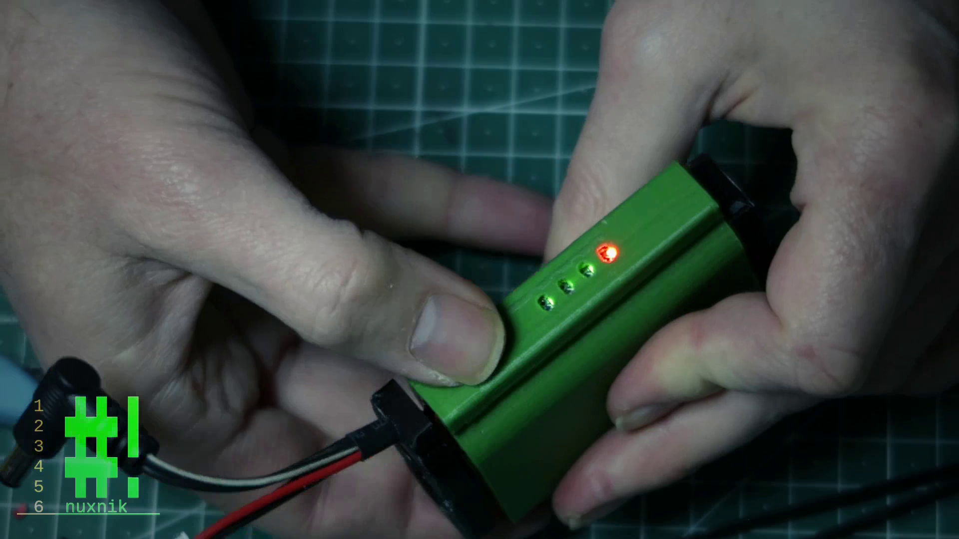
Next, we will solder all the positive leads to the exposed positive terminal of the battery. After soldering, check the voltage of each terminal, and end leads with a multi-meter. You can also press the button of the battery indicator. If it is lighting up and your multi-meter showed a plausible 2S voltage, you are good to go. Add the end caps on each side and secure them with two M2 screws.
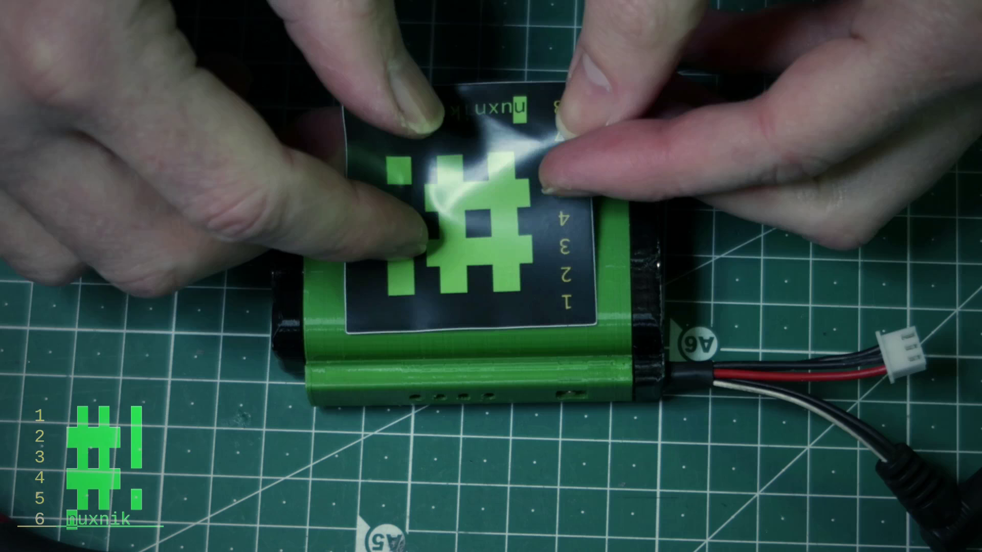
For one final touch, I have added my stickers to each side of the enclosure.
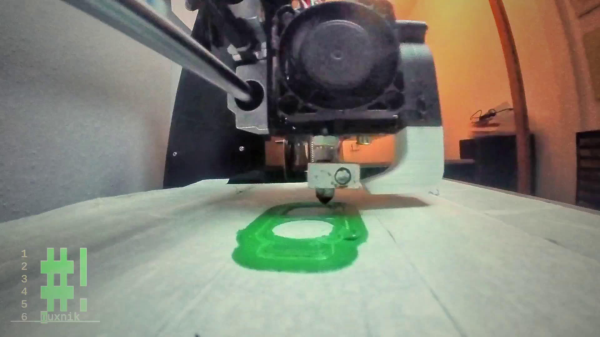
Build Video
Along with this article, I have created a build video you can follow along with:
Final Thoughts
Making this battery pack is very simple and is a good introduction to how battery packs function and what the extra wires are for. I hope you enjoyed my tutorial. Please leave a comment below with questions, or ideas on how this article could be improved. If you haven't already, subscribe to my YouTube Channel.