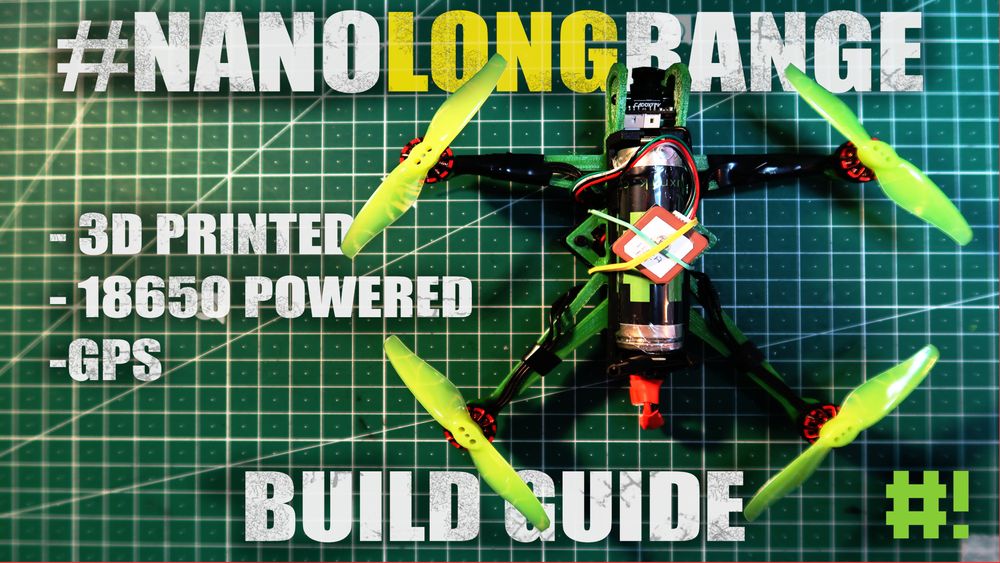
#NanoLongRange Build Guide
Synopsis
After watching Dave_C_FPV's YouTube video about his new project, I decided to take the plunge and build one myself. The thought of building a quadcopter with a printable frame and powering it on a single 1S 18650 battery is exciting. This document outlines my experience building the nano long range.
Required Tools
Below you'll find a list of the tools you will need to complete this project.
- 3D printer: Yes, this project will require a 3D Printer. If you don't own one, check to see if you have a local maker space in your area.
- Soldering Iron and Soldering Accessories: A soldering iron and soldering accessories are basic materials that anyone flying RC aircraft should own, Pick them up, they aren't expensive!
- Multimeter
Bill of Materials (BOM)
The materials and components required for this build can differ. With that said, there is no ONE correct way of building this drone. Many specific components can be swapped of others depending on your tastes or budget. The following list includes the components I used. Each link will redirect to the specific vendor, I bought each component from.
| Optional | Component | Price |
|---|---|---|
| DISCONTINUED - Eachine Nano V2 VTX | -- | |
| Foxeer Reaper Nano VTX | 16.69€ | |
| 18650 tray | 0.68€ | |
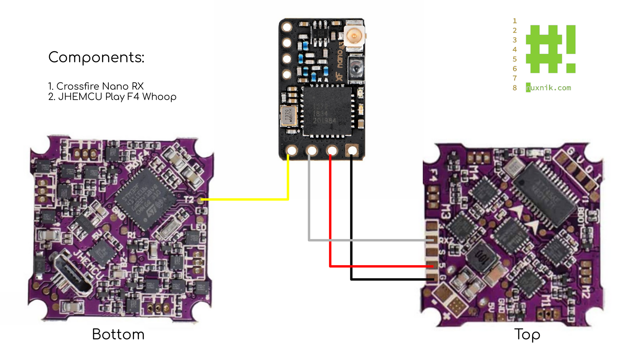
| Crossfire Nano RX | 20.00€ | |
| Caddx Ant Camera | 12.69€ | |
| LC filter | 3.42€ | |
| 5V Buck-Booster | 1.59€ | |
| DISCONTINUED - JHEMUC Play F4 FC | -- | |
| JHEMUC Ruibet f4AIO | 22.16€ | |
| Happymodel 1202.5 11000KV Motors | 31.91€ | |
| Gemfan 3018 Propellers | 7.39€ | |
| * | Beitian BN-180 GPS module | 16.26€ |
| * | Nylon Screws | 7.58€ |
| * | Nylon Standoffs | 3.45€ |
| Total: | 143.82€ |
Expensive? Maybe a little for a DIY drone, However, I have also listed optional components that aren't necessary. For example, the GPS module is completely optional, and the TBS Crossfire RX can be swapped for a cheaper receiver. The reason I chose this constellation of components is because I want to test the "Long Range" aspect of the name. How far can I push this little guy? Despite the seemingly high price tag, with a little searching, many of these components can be found for a cheaper price if your budget is tight.
Let's Build It!
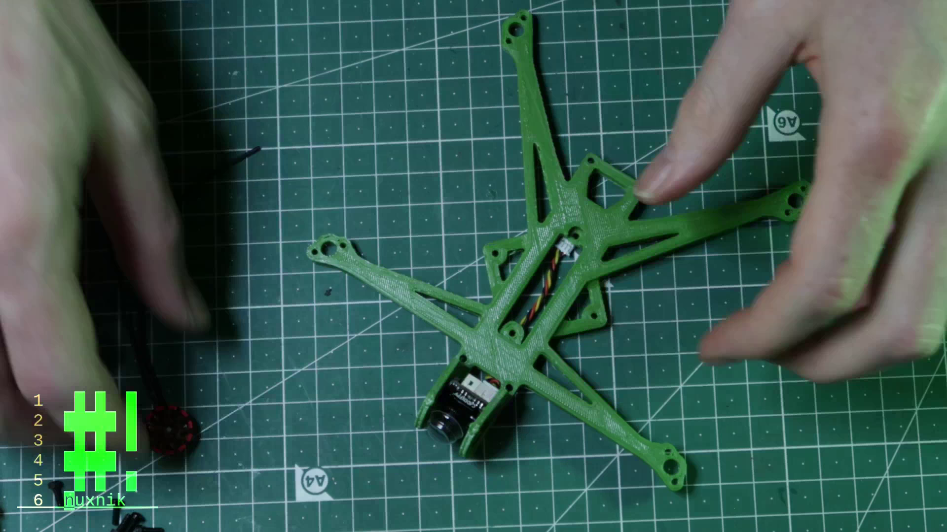
First thing's first - you need to print your frame. You can download the STL files from Dave_C's thingiverse build page. I used cura to slice the files and printed the frame in green and black PLA. The infill was set to 20% and the complete print took approximately 1.5 hours.
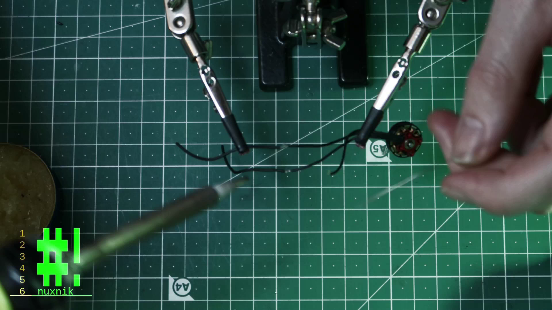
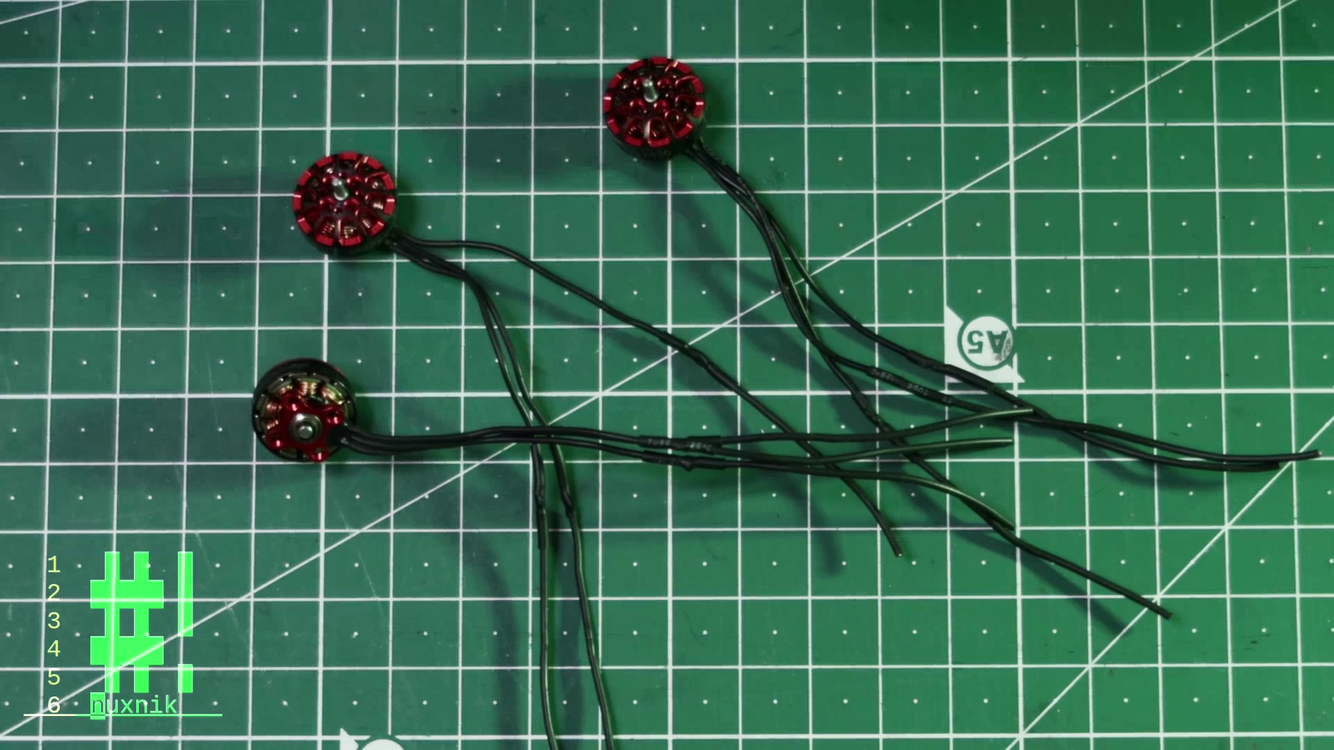
Extend Motor Wires
As stated above, I used Happymodel 1202.5 Motors. Unfortunately the wires were too short. This was easily fixed by adding an extra 5 centimeters to each wire. Firstly, I snipped off the motor plugs, stripped and tinned the wire ends and soldered the ends together with 28 AWG wire. The exposed solder joints were insulated with heat shrink tubing.
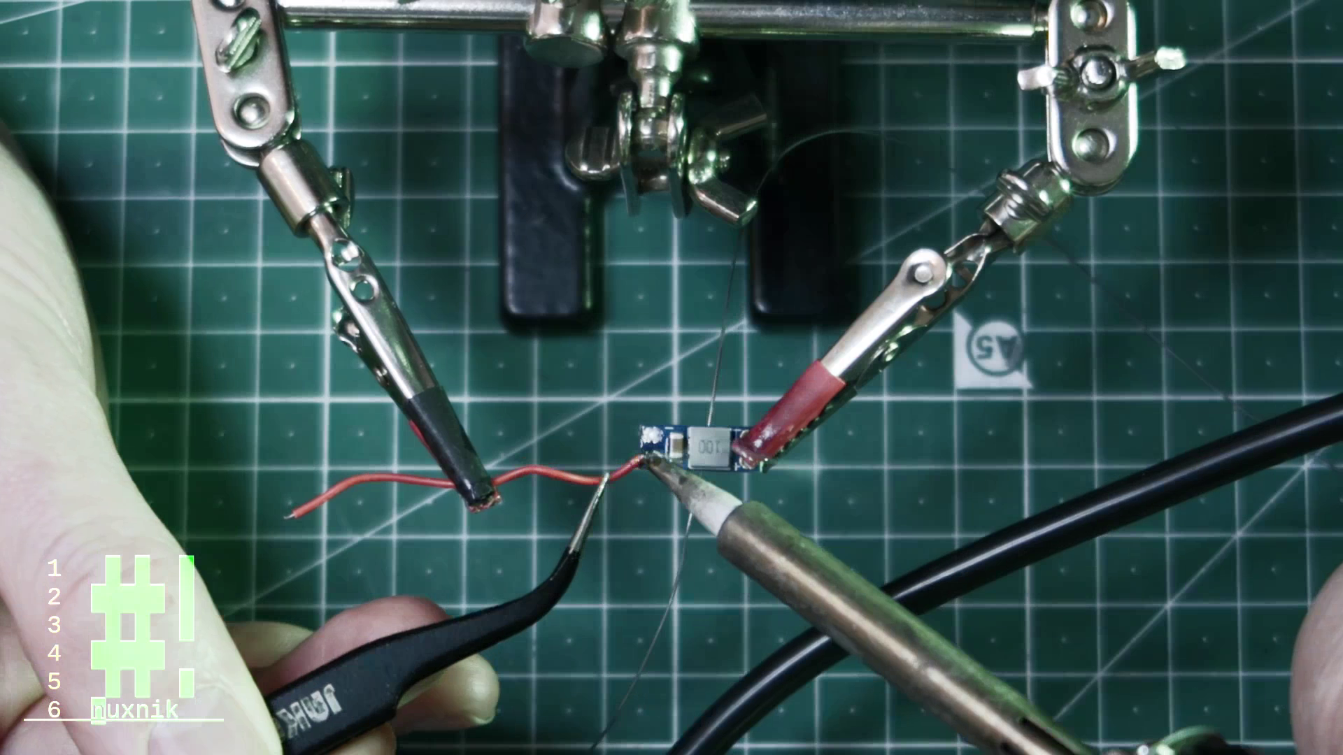
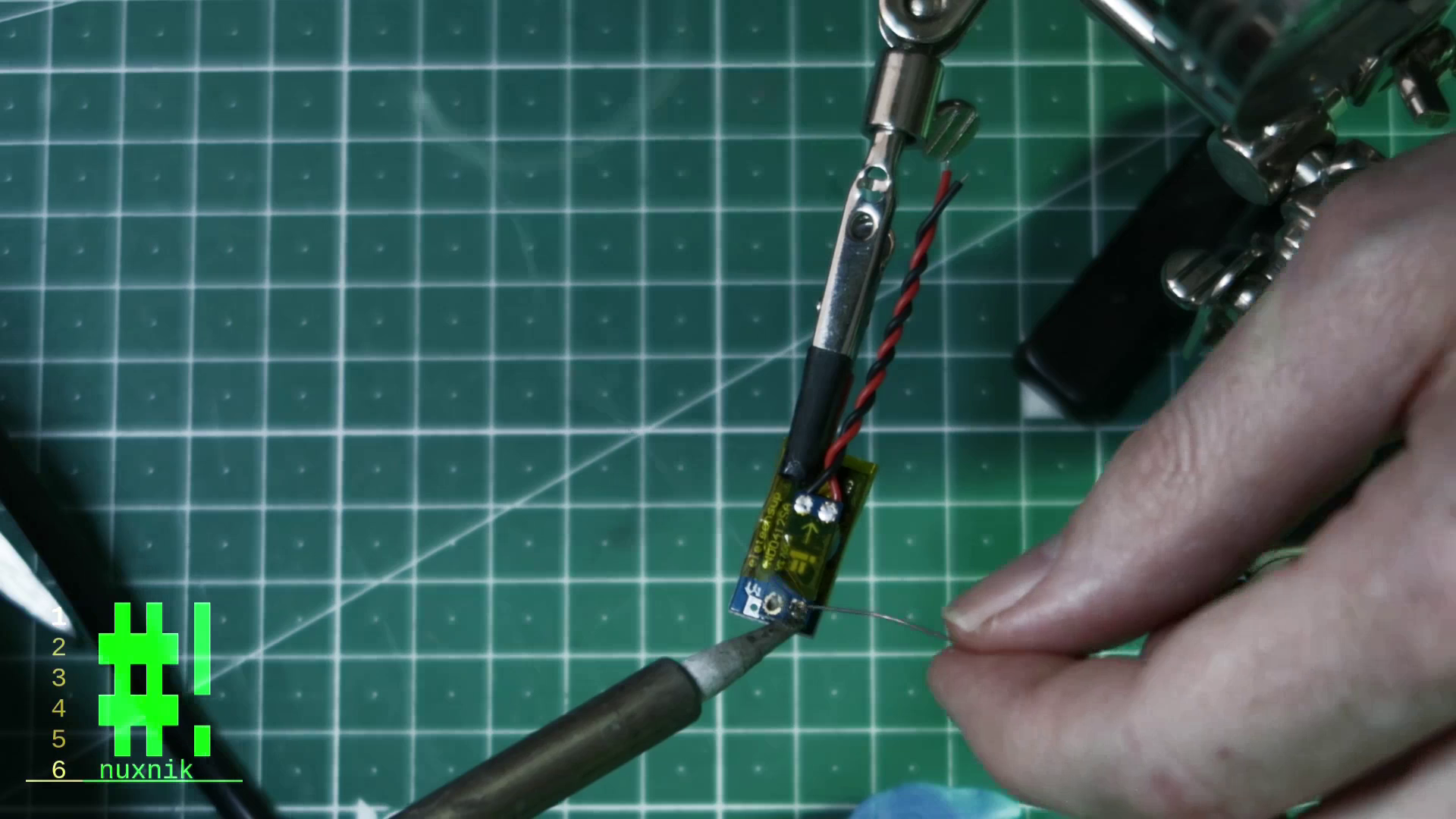
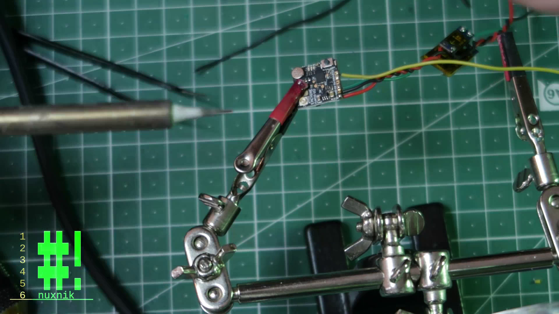
Buck-Booster and LC Filter
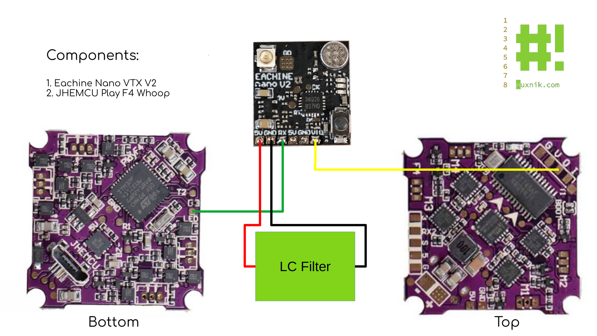
According to the following diagram, the LC filter and Buck-Booster are soldered together with the help of two header pins. Before connecting them, I wrapped each component in kapton tape. You could also insulate the boards with some heat shrink. Before proceeding, make sure to test the voltage output of both components. This can be done by connecting a bench-top power supply set to 4.2V. If you don't have a power supply, you can connect an 18650 directly to the power leads. The output should be 5V. If it is not, recheck your wiring!
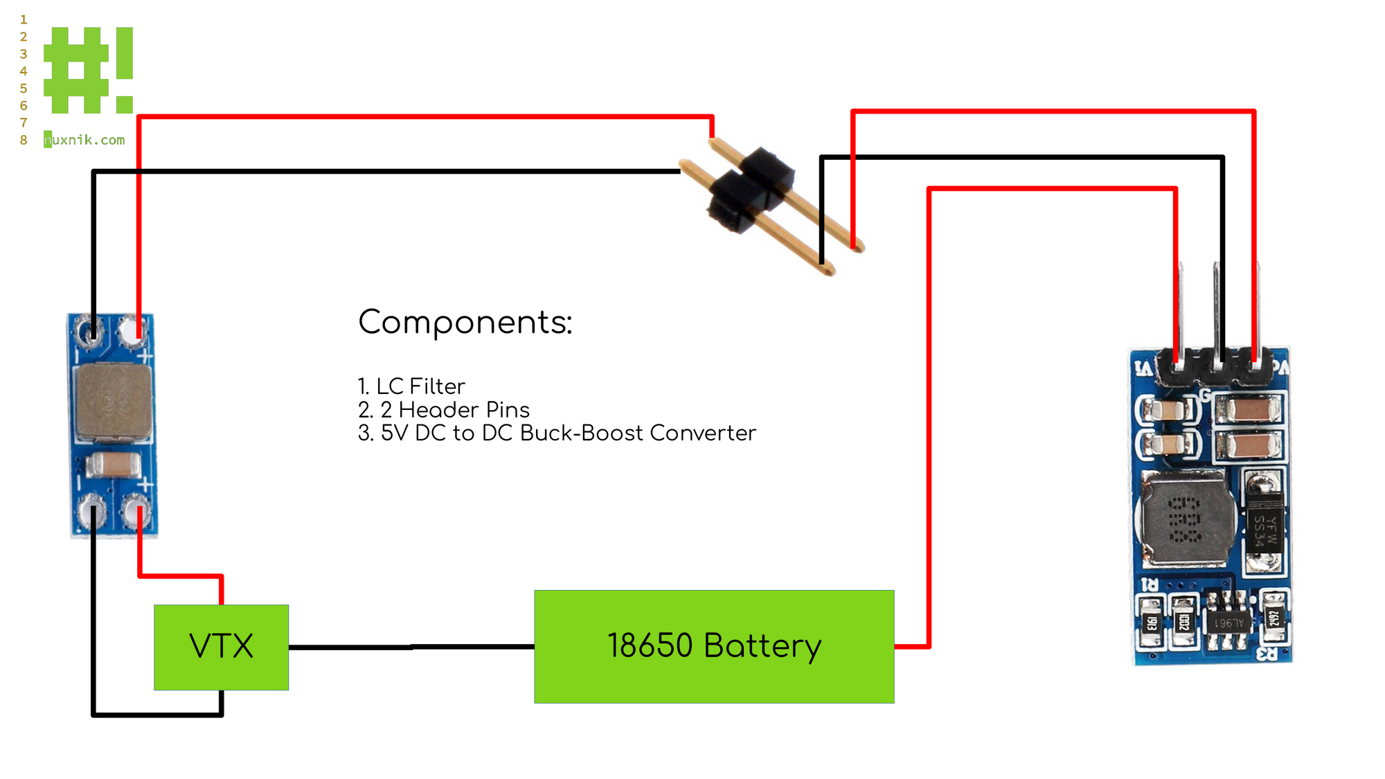
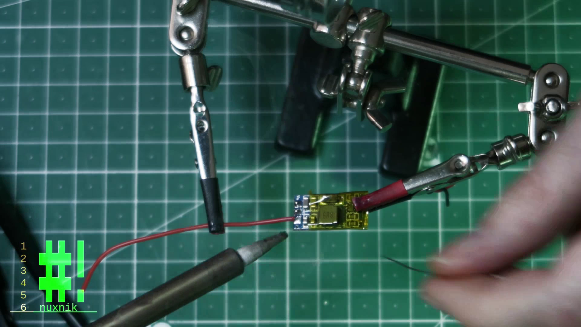
Constructing the LC Filter and Buck-Boost Converter
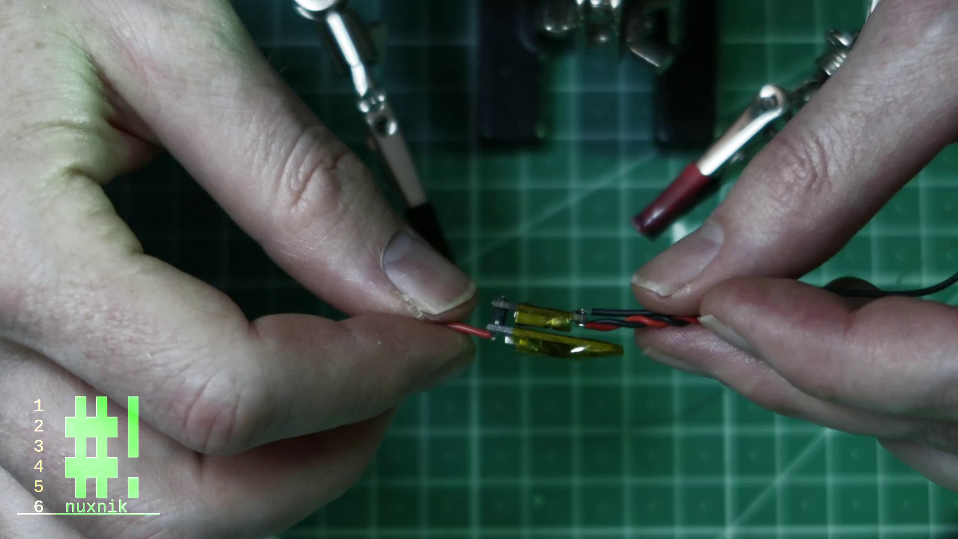
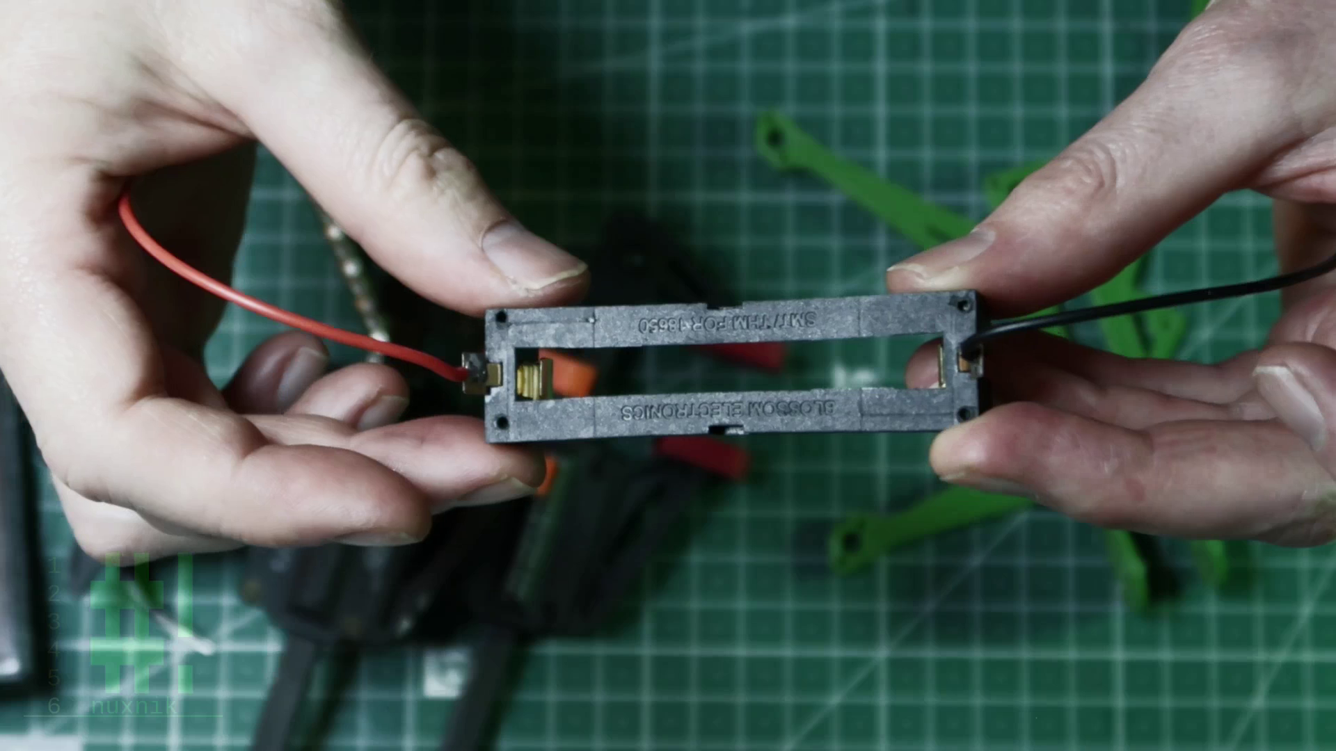
Battery Tray
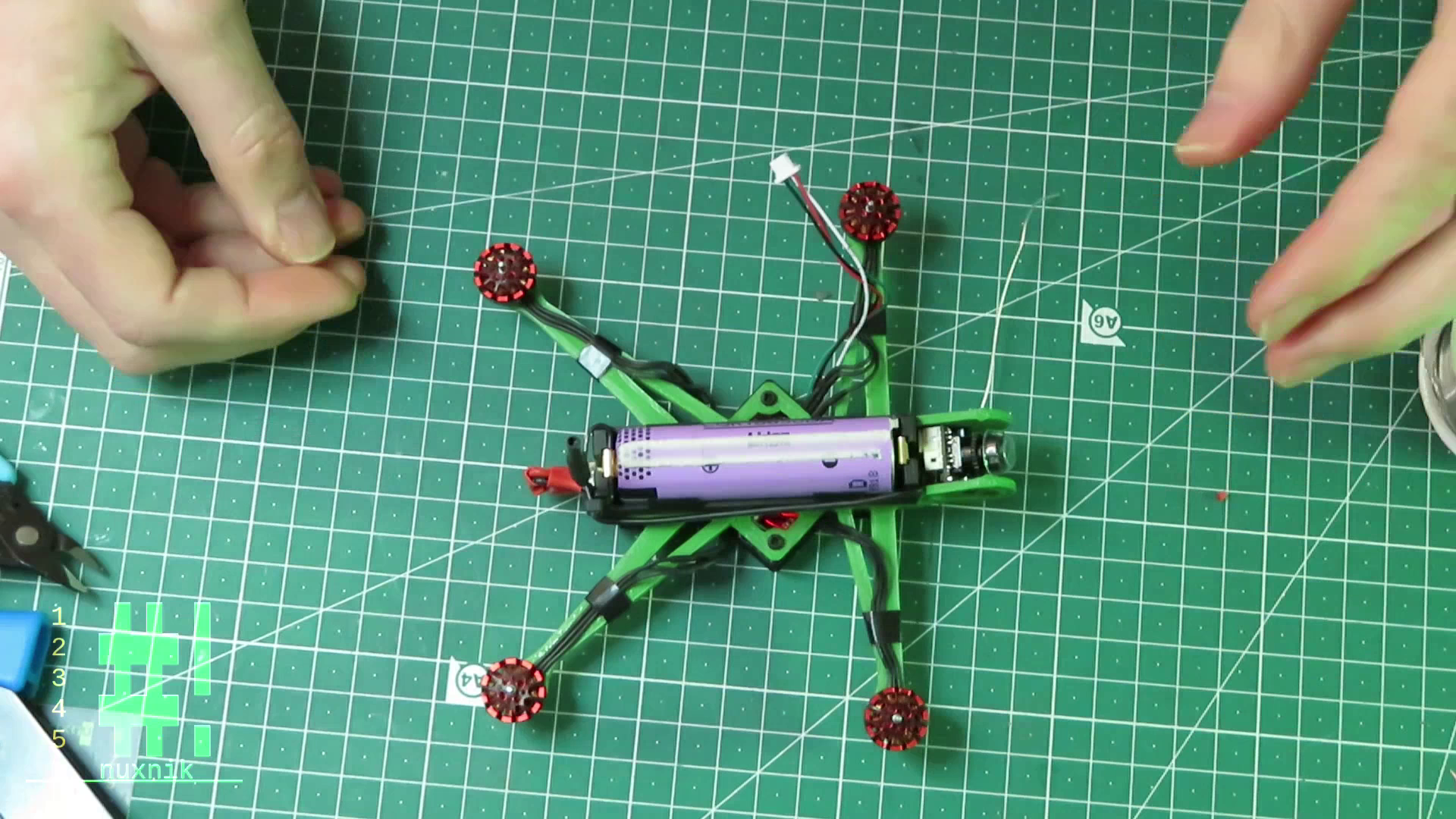
The battery tray can now be prepped. Firstly, solder power leads to the plus/minus terminals. Each lead should be approximately 8-10 cm. With the help of some small clamps I, secured the battery holder onto the 3D printed frame. I used a small hand drill to drill out the mounting holes for the screws. The clamps held the battery tray in place so that I could use the screw holes in the frame as a template. The drill bit I used was slightly smaller than 2mm diameter so that the screws would have something to grip onto when everything is put together.
Mounting Peripherals
The following components can now be added to the main frame:
- Caddx Camera
- 4 x Motors
- M2 Nylon standoffs for the flight controller
After the components have been mounted, you can measure the correct length of the wires and shorten them accordingly.
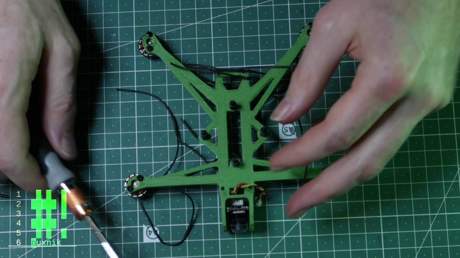
Mounting the camera and the motors
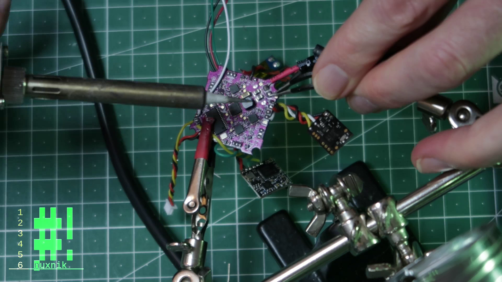
Flight Controller Prep
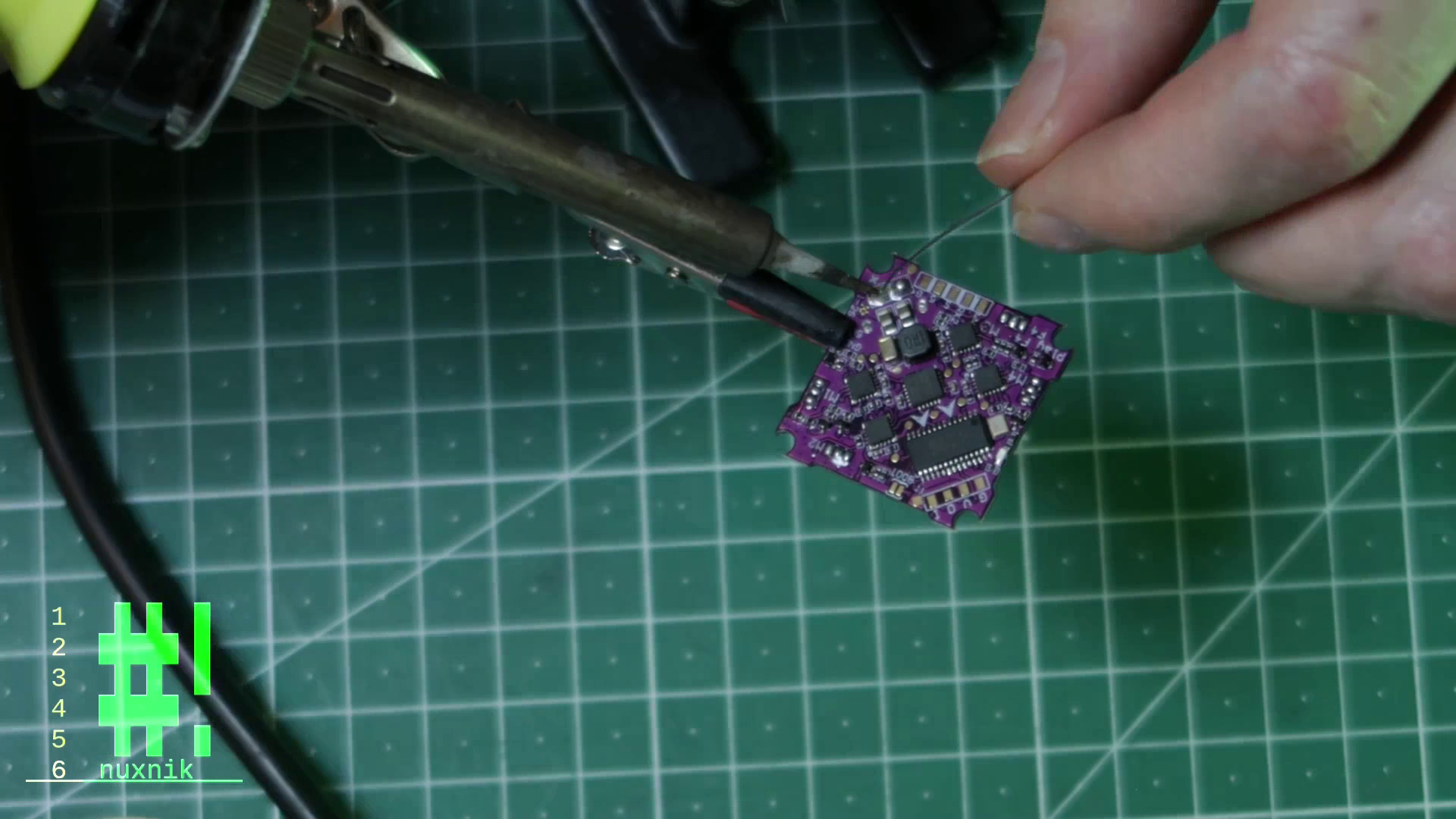
At this stage, it is a good idea to tin the solder pads of the flight controller. This will make the build move a little smoother as we add the peripheral modules. Make sure to use plenty of solder flux. This will make your life a lot easier while soldering on such a tiny board.
Wiring up the Receiver
In my case I am using a crossfire nano receiver. This receiver requires a RX and TX UART pad. For the received I am using UART 2. The connection is simple enough - 5V to 5V, ground to ground, TX to RX and RX to TX.
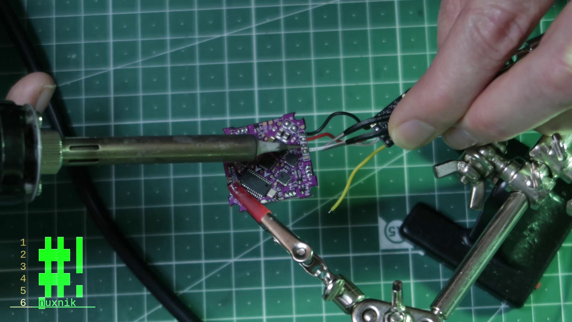
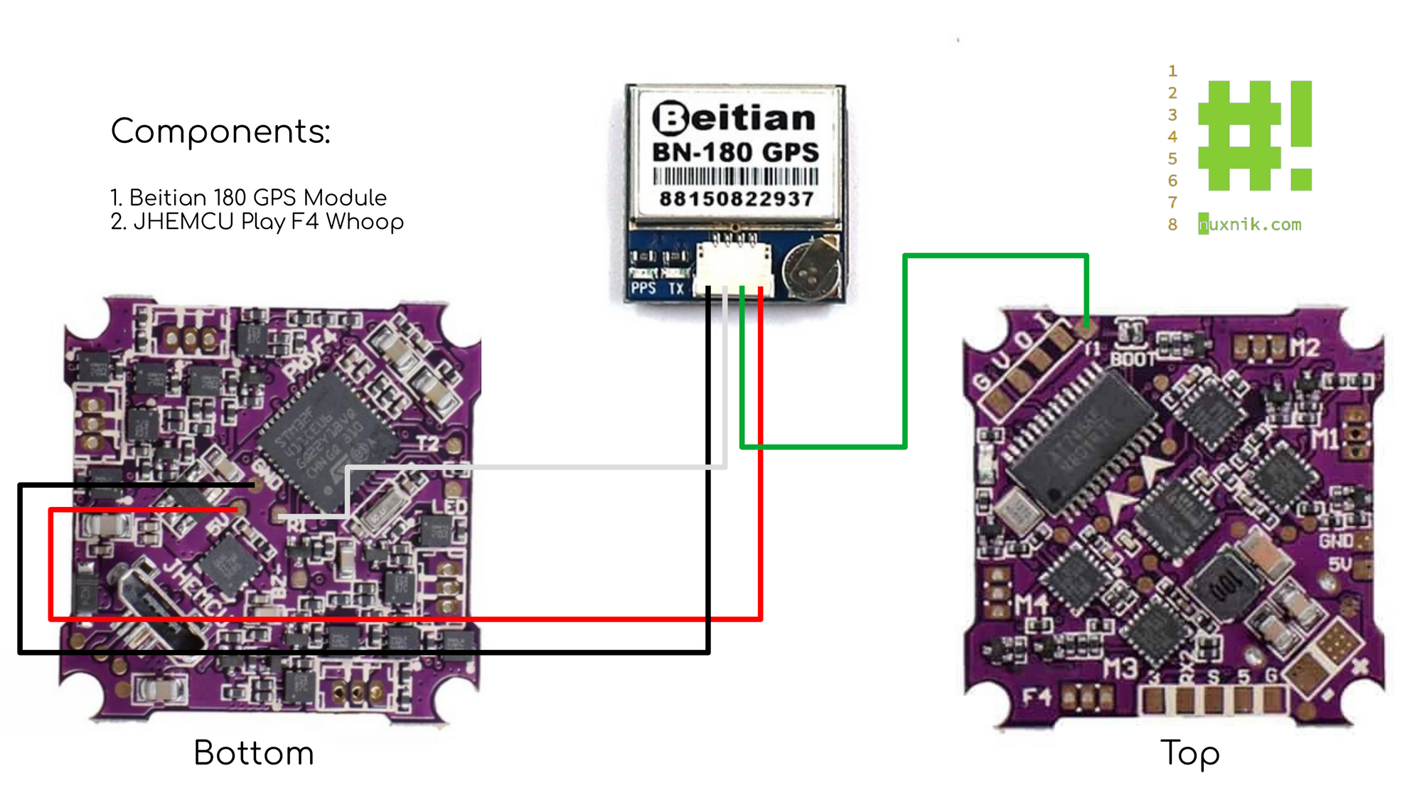
Wiring up the GPS Module
This is an optional step and can be skipped if you decide not to use a GPS module. The Beitain BN-180 module also requires both and RX and TX pad. For this module, I am using UART 1. Extra care needs to be taken when soldering these wires. The pads are tiny and in middle of the board. Make sure you don't bridge any other contacts and make sure to use solder flux.
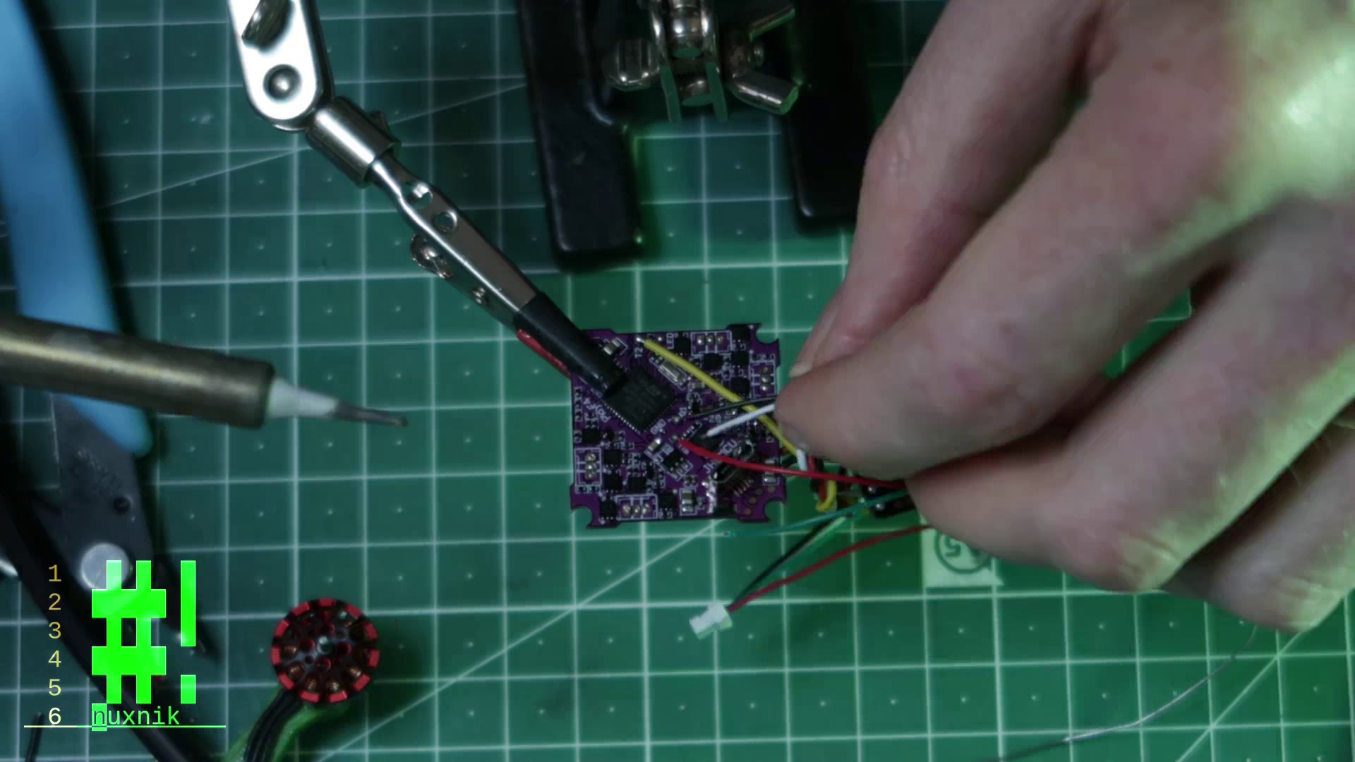
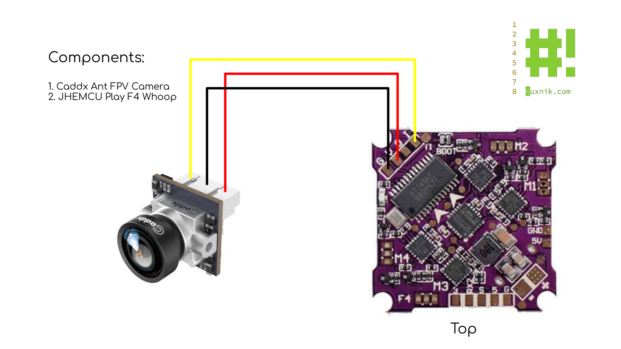
Wiring up the Camera
The camera is straight forward and the pads are clearly labeled on the FC. 5V to 5V, ground to ground and camera output to camera input.
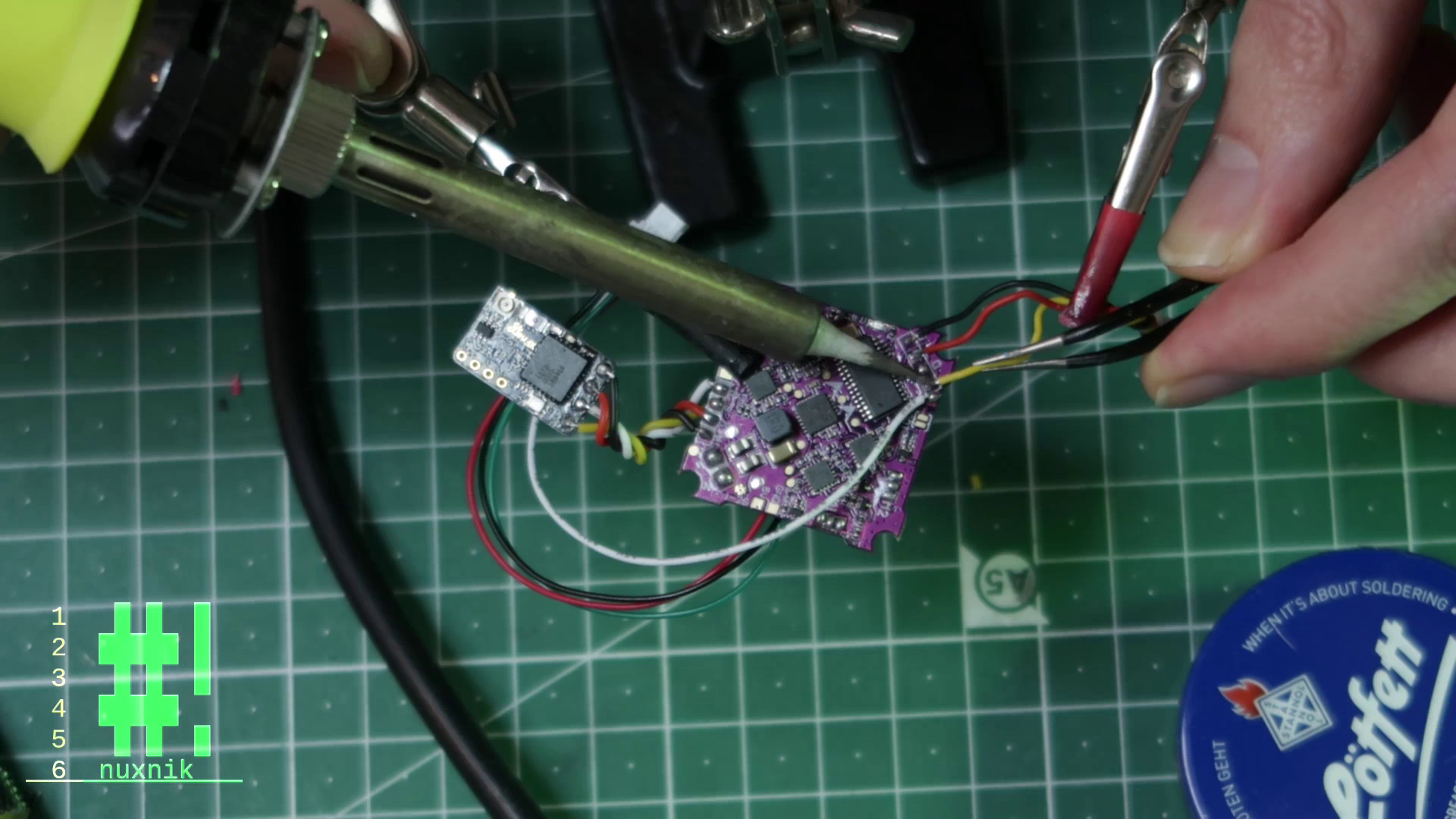
Wiring up the Video Transmitter
The VTX will be powered through out buck-booster/LC filter in order to supply 5 volts and to clean up the video signal. This is necessary since it is being powered directly from the battery. I am also connecting the RX of the VTX to the LED_STRIP pad of the flight controller. This will be mapped later using Softserial in BetaFlight. That way we will be able to modify the VTX setting via SmartAudio. The ground wire from the VTX is connected to a ground pad of the flight controller.
Wiring up the Capacitor and Power Leads
The capacitor and power leads can now be connected. Since this is an electrolytic capacitor, make sure to pay attention to the polarity. Next, the positive wire from the Buck-Booster is soldered to the positive pad of the flight controller. Looks like we're done wiring, we can now assemble the rest of the frame.
Short Circuit Check
Before plugging in you battery, a short circuit check should be done to make sure you don't destroy your flight controller or connected modules when you plug in the battery. Take your multi-meter and check for continuity between the positive and ground terminals of your battery. If it checks out, you should be relatively safe snapping in an 18650 into the battery tray.
Configuration in Betaflight
We have built our quad, now let's configure it! Connect your freshly made drone via USB to your computer and open BetaFlight.
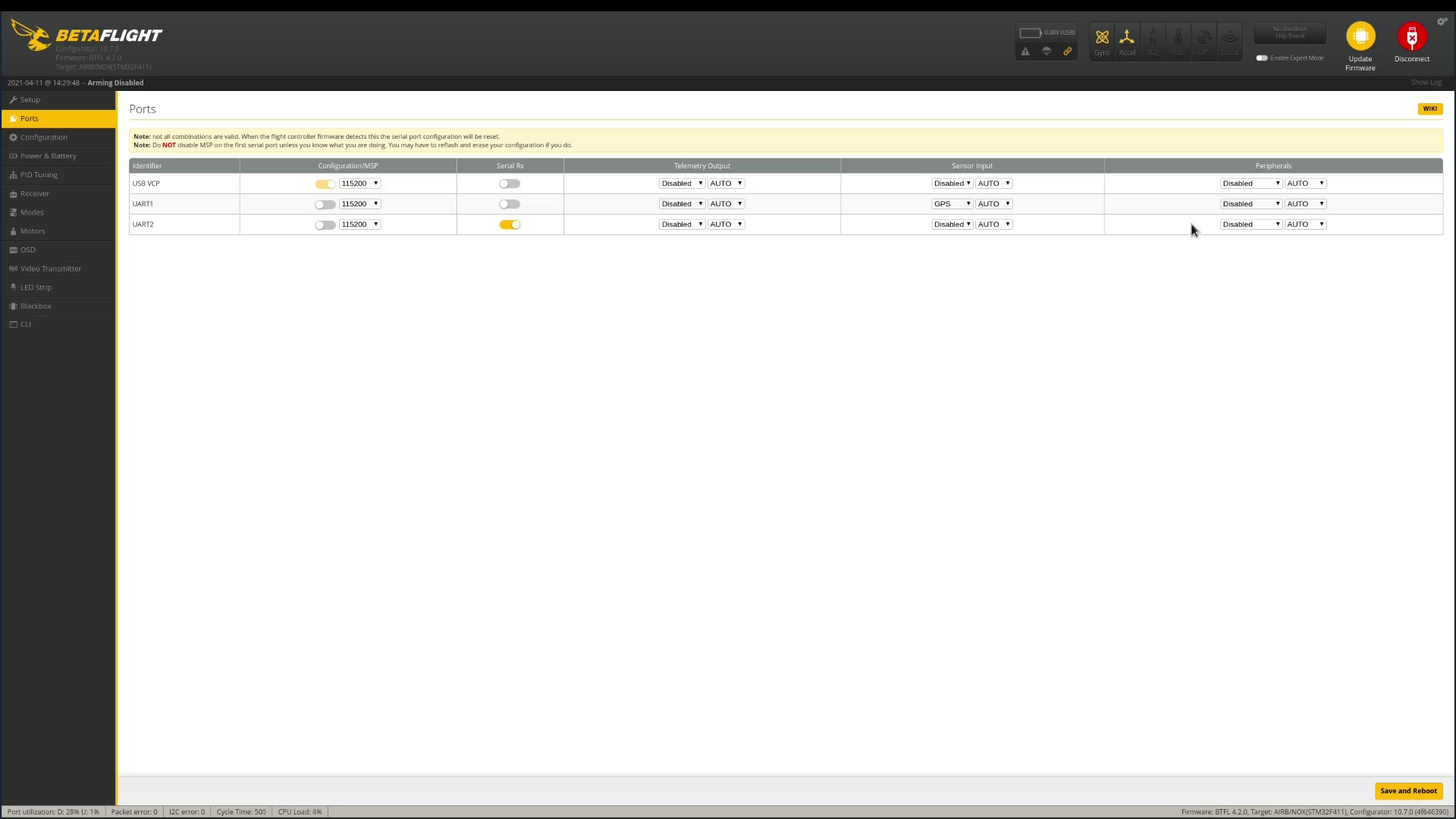
Ports
Go to "Ports" and change the following settings
Softserial
Since we are using an F4 flight controller, we are limited to two UARTS. Note, the following step is only necessary if you decide to add a GPS module. This is entirely optional. For more information on what SoftSerial is check out Oscar Liang's Article on the subject.
Open Betaflight and click on the CLI option. We are going to map a softserial TX to the LED_STRIP resource.
resource LED_STRIP none
Reassign the SoftSerial TX to the to resource
resource SERIAL_TX 12 a000
Save the settings
save
VTX Table:
The following VTX table is specific to the Eachine Nano VTX. If you are using a different VTX, these settings can be different. Open Betaflight and click on the CLI option and paste the following code into the input field:
vtxtable bands 5
vtxtable channels 8
vtxtable band 1 BOSCAM_A A CUSTOM 5865 5845 5825 5805 5785 5765 5745 5725
vtxtable band 2 BOSCAM_B B CUSTOM 5733 5752 5771 5790 5809 5828 5847 5866
vtxtable band 3 BOSCAM_E E CUSTOM 5705 5685 5665 5645 5885 5905 5925 5945
vtxtable band 4 FATSHARK F CUSTOM 5740 5760 5780 5800 5820 5840 5860 5880
vtxtable band 5 RACEBAND R CUSTOM 5658 5695 5732 5769 5806 5843 5880 5917
vtxtable powerlevels 4
vtxtable powervalues 25 100 200 400
vtxtable powerlabels 25 100 200 400
save
After pasting the code press enter. This will reboot the drone. In order to check whether the settings were saved click on the VTX tab and have a look at the settings. Once there you can set you default channel and mW output.
PIDs
The following PIDs were taken from Dave_C's Thingiverse build page. I have tested these settings with my own quad and found them to work well. In order to save them to your flight controller, click on the CLI option in Betaflight and paste the following code into the input field:
set p_pitch = 100
set i_pitch = 50
set d_pitch = 70
set f_pitch = 125
set p_roll = 90
set i_roll = 45
set d_roll = 65
set f_roll = 125
set p_yaw = 65
set i_yaw = 20
set d_yaw = 0
set f_yaw = 125
save
After pasting the code press enter. This will reboot the drone. In order to check whether the settings were saved click on the PID tab and have a look at the settings.
Further Configuration
The rest of the configuration goes beyond the scope of this tutorial and is specific to the components you have. If you have used the same components as I, then feel free to follow along in my build video listed at the bottom of this article.
Build Video
For your convenience, I have created a build video based on this post. In the video I covered every step posted here. If you are curious as to how this little machine flies, I also included a flight test. Check it out and while you're at it, subscribe to my channel.
#NanoLongRange Build Guide
#NanoLongRange Flight Test
#NanoLongRange + Insta360 Go - Will it fly?
Airvuz
If you aren't the biggest fan of the YouTube platform, you can also check out my build video on Airvuz.
Thoughts
The complete build took approximately 6 hours to complete. It is not the easiest DIY drone to build and I would not recommended it for someone new to soldering and electronics. However, the satisfaction of flying something that you have made yourself, makes any headaches worth the effort. I would like to thank Dave_C for the hard work that went into his creative design.
Help Out
If this tutorial helped you in any way and you like what you read, send me some Satoshis and buy me a coffee. :)
12dxt1JsQnJhyhZPAr2b2xvzGyR9BgpncN
... or join me on Patreon
Links and References
The #NanoLongRange on Thingiverse